


8XC251SA, SB, SP, SQ USER’S MANUAL
14-6
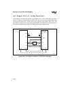
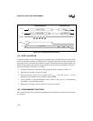
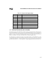
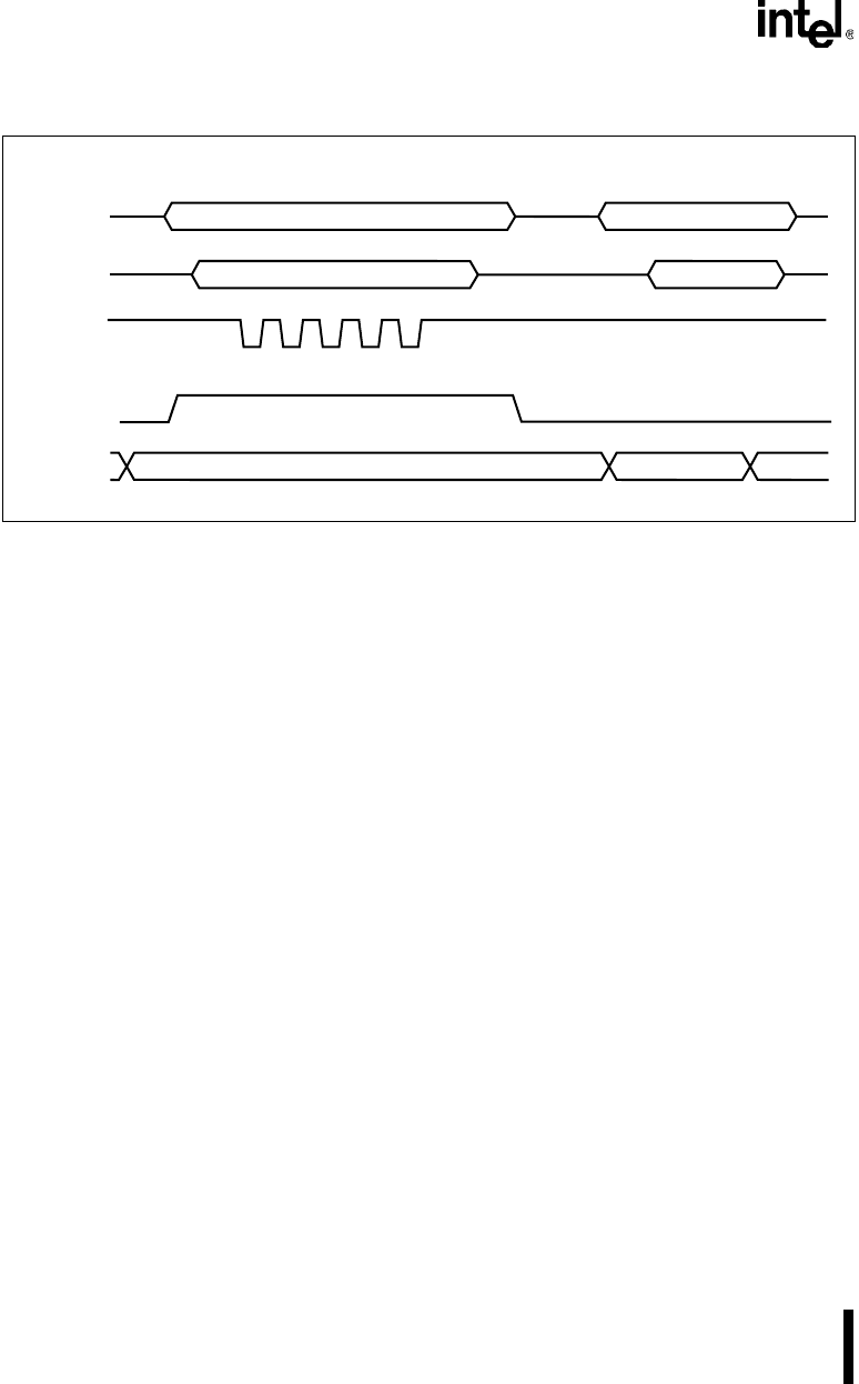
Figure 14-2. Program/Verify Bus Cycles
14.5 VERIFY ALGORITHM
Use this procedure to verify user program code, signature bytes, configuration bytes, and lock bits
stored in nonvolatile memory on the 8XC251Sx. To preserve the secrecy of the encryption key
byte sequence, the encryption array cannot be verified. Verification can be performed on bytes as
they are programmed, or on a block of bytes that have been previously programmed. The proce-
dure for verifying the 8XC251Sx is as follows:
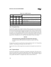
1. Set up the controller for operation in the appropriate mode according to Table 14-1.
2. Input the 16-bit address on ports P1 and P3.
3. Wait for the data on port P2 to become valid (T
AVQV
= 48 clock cycles — see the
datasheet), then compare the data with the expected value.
4. If the procedure is program/immediate-verify, return to step 8 of 14.4, “Programming
Algorithm,” to program the next byte.
5. Repeat steps 1 through 5 until all memory locations are verified.
14.6 PROGRAMMABLE FUNCTIONS
This section discusses factors related to programming and verifying the various nonvolatile mem-
ory functions.
PROG#
EA#/V
PP
P1, P3
A4129-01
AddressAddress (16-Bit)
P2
Data Out
Data In (8-Bit)
12345
P0
Mode
Mode (8-Bit)
12.75V
Programming Cycle Verification Cycle
5V