


8XC251SA, SB, SP, SQ USER’S MANUAL
C-30
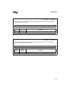
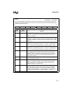
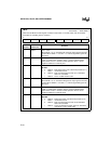
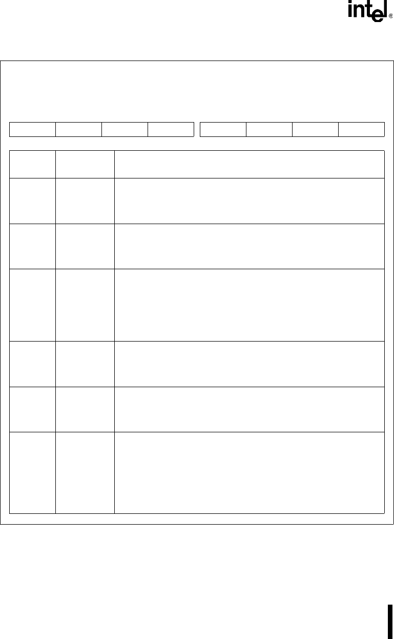
TMOD
Address: S:89H
Reset State: 0000 0000B
Timer/Counter Mode Control Register. Contains mode select, run control select, and counter/timer
select bits for controlling timer 0 and timer 1.
7 0
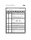
GATE1 C/T1# M11 M01 GATE0 C/T0# M10 M00
Bit
Number
Bit
Mnemonic
Function
7 GATE1 Timer 1 Gate:
When GATE1 = 0, run control bit TR1 gates the input signal to the timer
register. When GATE1 = 1 and TR1 = 1, external signal INT1 gates the
timer input.
6 C/T1# Timer 1 Counter/Timer Select:
C/T1# = 0 selects timer operation: timer 1 counts the divided-down
system clock. C/T1# = 1 selects counter operation: timer 1 counts
negative transitions on external pin T1.
5, 4 M11, M01 Timer 1 Mode Select:
M11 M01
0 0 Mode 0: 8-bit timer/counter (TH1) with 5-bit prescalar (TL1)
0 1 Mode 1: 16-bit timer/counter
1 0 Mode 2: 8-bit auto-reload timer/counter (TL1). Reloaded
from TH1 at overflow.
1 1 Mode 3: Timer 1 halted. Retains count.
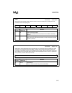
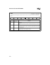
3 GATE0 Timer 0 Gate:
When GATE0 = 0, run control bit TR0 gates the input signal to the timer
register. When GATE0 = 1 and TR0 = 1, external signal INT0 gates the
timer input.
2 C/T0# Timer 0 Counter/Timer Select:
C/T0# = 0 selects timer operation: timer 0 counts the divided-down
system clock. C/T0# = 1 selects counter operation: timer 0 counts
negative transitions on external pin T0.
1, 0 M10, M00 Timer 0 Mode Select:
M10 M00
0 0 Mode 0: 8-bit timer/counter (T0) with 5-bit prescaler (TL0)
0 1 Mode 1: 16-bit timer/counter
1 0 Mode 2: 8-bit auto-reload timer/counter (TL0). Reloaded
from TH0 at overflow.
1 1 Mode 3: TL0 is an 8-bit timer/counter. TH0 is an 8-bit timer
using timer 1’s TR1 and TF1 bits.