8XC251SA, SB, SP, SQ USER’S MANUAL
12-2
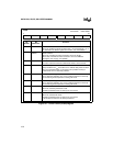
Figure 12-1. Power Control (PCON) Register
PCON
Address: S:87H
Reset State: 00XX 0000B
7 0
SMOD1 SMOD0 — POF GF1 GF0 PD IDL
Bit
Number
Bit
Mnemonic
Function
7 SMOD1 Double Baud Rate Bit:
When set, doubles the baud rate when timer 1 is used and mode 1, 2, or
3 is selected in the SCON register. See section 10.6, “Baud Rates.”
6 SMOD0 SCON.7 Select:
When set, read/write accesses to SCON.7 are to the FE bit.
When clear, read/write accesses to SCON.7 are to the SM0 bit.
See Figure 10-2 on page 10-3 (SCON).
5 — Reserved:
The value read from this bit is indeterminate. Write a zero to this bit.
4 POF Power Off Flag:
Set by hardware as V
CC
rises above 3 V to indicate that power has been
off or V
CC
had fallen below 3 V and that on-chip volatile memory is
indeterminate. Set or cleared by software.
3 GF1 General Purpose Flag:
Set or cleared by software. One use is to indicate whether an interrupt
occurred during normal operation or during idle mode.
2 GF0 General Purpose Flag:
Set or cleared by software. One use is to indicate whether an interrupt
occurred during normal operation or during idle mode.
1 PD Powerdown Mode Bit:
When set, activates powerdown mode.
Cleared by hardware when an interrupt or reset occurs.
0 IDL Idle Mode Bit:
When set, activates idle mode.
Cleared by hardware when an interrupt or reset occurs.
If IDL and PD are both set, PD takes precedence.


