


A-103
INSTRUCTION SET REFERENCE
NOP
Function: No operation
Description: Execution continues at the following instruction. Affects the PC register only.
Flags:
Example: You want to produce a low-going output pulse on bit 7 of Port 2 that lasts exactly 11 states. A
simple CLR-SETB sequence generates an eight-state pulse. (Each instruction requires four
states to write to a port SFR.) You can insert three additional states (if no interrupts are
enabled) with the following instruction sequence:
CLR P2.7
NOP
NOP
NOP
SETB P2.7
Binary Mode Source Mode
Bytes: 11
States: 11
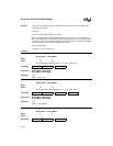
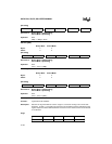
Hex Code in: Binary Mode = [Encoding]
Source Mode = [Encoding]
Operation: NOP
(PC) ← (PC) + 1
ORL <dest> <src>
Function: Logical-OR for byte variables
Description: Performs the bitwise logical-OR operation (V) between the specified variables, storing the
results in the destination operand.
The destination operand can be a register, an accumulator or direct address.
The two operands allow twelve addressing mode combinations. When the destination is the
accumulator, the source can be register, direct, register-indirect, or immediate addressing;
when the destination is a direct address, the source can be the accumulator or immediate
data. When the destination is register the source can be register, immediate, direct and
indirect addressing.
Note: When this instruction is used to modify an output port, the value used as the original
port data is read from the output data latch, not the input pins.
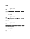
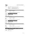
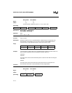
Flags:
CY AC OV N Z
—————
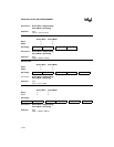
[Encoding] 0 0 0 0 0 0 0 0
CY AC OV N Z
———✓✓