


13-29
EXTERNAL MEMORY INTERFACE
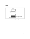
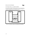
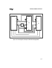
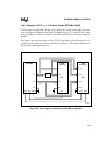
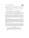
13.8.6 Example 6: RD1:0 = 11, 16-bit Bus, External EPROM and RAM
In this example, an 80C251SB operates in page mode with a 16-bit external address bus inter-
faced to 64 Kbytes of EPROM and 64 Kbytes of RAM (Figure 13-27). The 80C251SB is config-
ured so that RD# is asserted for addresses ≤ 7F:FFFFH, and PSEN# is asserted for addresses ≥
80:0000.
This system is the same as Example 5 (Figure 13-25) except that it operates in page mode. Ac-
cordingly, the two systems have the same memory map (Figure 13-26), and the comments on ad-
dressing external RAM apply here also.
Figure 13-27. Bus Diagram for Example 6: 80C251SB in Page Mode
A4146-01
A7:0
A15:8/D7:0
A15:8
Latch
PSEN#
80C251SB
RD#
WR#
P2
P0
EA#
EPROM
(64 Kbytes)
OE#
D7:0
A15:8
A7:0
CE# CE#
A15:8
A7;0
RAM
(64 Kbytes)
D7:0
OE#
WE#
Code
Data