


A-17
INSTRUCTION SET REFERENCE
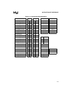
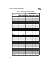
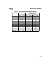
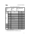
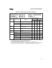
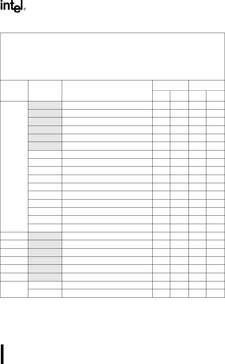
Table A-23. Summary of Logical Instructions
Logical AND ANL <dest>,<src> dest opnd ←dest opnd Λ src opnd
Logical OR ORL <dest>,<src> dest opnd ← dest opnd V src opnd
Logical Exclusive OR XRL <dest>,<src> dest opnd ← dest opnd ∀ src opnd
Clear CLR A (A) ← 0
Complement CPL A (Ai) ← Ø(Ai)
Rotate RXX A (1)
Shift SXX Rm or Wj (1)
SWAP A A3:0 ↔ A7:4
Mnemonic <dest>,<src> Notes
Binary Mode Source Mode
Bytes States Bytes States
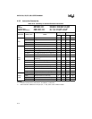
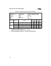
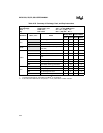
ANL;
ORL;
XRL;
A,Rn Reg to acc 1 1 2 2
A,dir8 Dir byte to acc 2 1 (3) 2 1 (3)
A,@Ri Indir addr to acc 1 2 2 3
A,#data Immediate data to acc 2 1 2 1
dir8,A Acc to dir byte 2 2 (4) 2 2 (4)
dir8,#data Immediate data to dir byte 3 3 (4) 3 3 (4)
Rmd,Rms Byte reg to byte reg 3 2 2 1
WRjd,WRjs Word reg to word reg 3 3 2 2
Rm,#data 8-bit data to byte reg 4 3 3 2
WRj,#data16 16-bit data to word reg 5 4 4 3
Rm,dir8 Dir addr to byte reg 4 3 (3) 3 2 (3)
WRj,dir8 Dir addr to word reg 4 4 3 3
Rm,dir16 Dir addr (64K) to byte reg 5 3 4 2
WRj,dir16 Dir addr (64K) to word reg 5 4 4 3
Rm,@WRj Indir addr (64K) to byte reg 4 3 3 2
Rm,@DRk Indir addr (16M) to byte reg 4 4 3 3
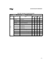
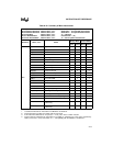
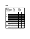
CLR
A Clear acc 1 1 1 1
CPL
A Complement acc 1 1 1 1
RL
A Rotate acc left 1 1 1 1
RLC
A Rotate acc left through the carry 1 1 1 1
RR
A Rotate acc right 1 1 1 1
RRC
A Rotate acc right through the carry 1 1 1 1
SLL
Rm Shift byte reg left 3 2 2 1
WRj Shift word reg left 3 2 2 1
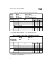
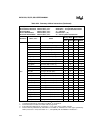
NOTES:
1. See section A.4, “Instruction Descriptions.”
2. A shaded cell denotes an instruction in the MCS
®
51 architecture.
3. If this instruction addresses an I/O port (P
x
,
x
= 0–3), add 1 to the number of states.
4. If this instruction addresses an I/O port (P
x
,
x
= 0–3), add 2 to the number of states.