


11-1
CHAPTER 11
MINIMUM HARDWARE SETUP
This chapter discusses the basic operating requirements of the MCS
®
251 microcontroller and de-
scribes a minimum hardware setup. Topics covered include power, ground, clock source, and de-
vice reset. For parameter values, refer to the device data sheet.
11.1 MINIMUM HARDWARE SETUP
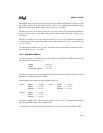
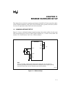
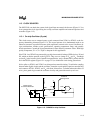
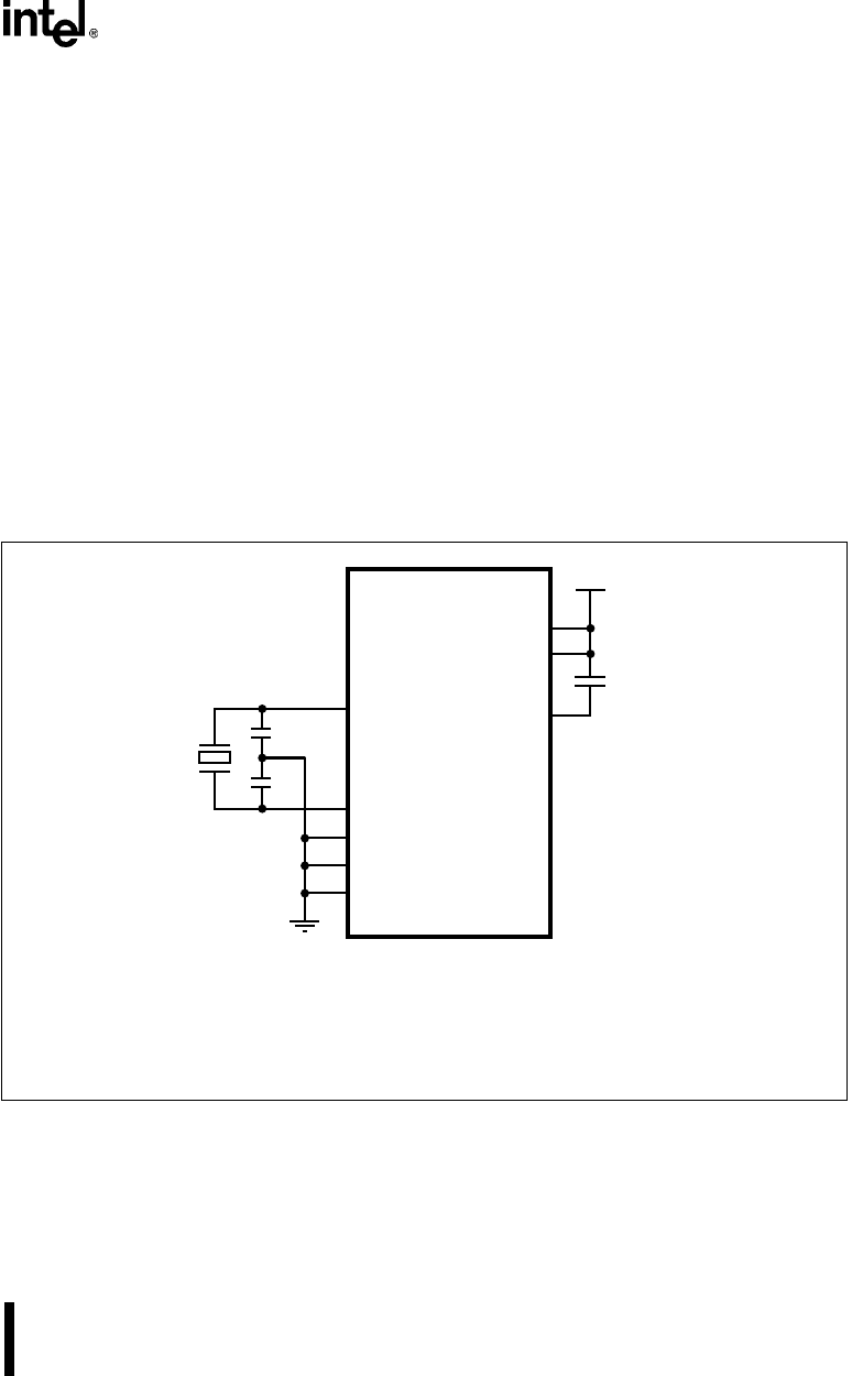
Figure 11-1 shows a minimum hardware setup that employs the on-chip oscillator for the system
clock and provides power-on reset. Control signals and Ports 0, 1, 2, and 3 are not shown. See
sections 11.3, “Clock Sources” and 11.4.4, “Power-on Reset.”
Figure 11-1. Minimum Setup
8XC251S
x
A4141-02
XTAL2
V
SS
V
CC
V
CC
XTAL1
RST
C1
V
SS1
C2
1µF
+
Note:
V
CC2
is a secondary power pin that reduces power supply noise. V
SS1
and V
SS2
are
secondary ground pins that reduce ground bounce and improve power supply by-passing.
Connections to these pins are not required for proper device operation.
V
CC2
V
SS2