


9-9
PROGRAMMABLE COUNTER ARRAY
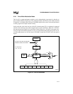
The user also has the option of generating an interrupt request when the match occurs by setting
the corresponding interrupt enable bit (ECCFx in the CCAPMx register). Since hardware does not
clear the compare/capture flag when the interrupt is processed, the user must clear the flag in soft-
ware.
If the user does not change the compare/capture registers in the interrupt routine, the next toggle
occurs after the PCA timer/counter rolls over and the count again matches the comparison value.
During the interrupt routine, a new 16-bit compare value can be written to the compare/capture
registers (CCAPxH/CCAPxL).
NOTE
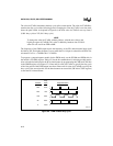
To prevent an invalid match while updating these registers, user software
should write to CCAPxL first, then CCAPxH. A write to CCAPxL clears the
ECOMx bit disabling the compare function, while a write to CCAPxH sets the
ECOMx bit re-enabling the compare function.
9.3.5 PCA Watchdog Timer Mode
A watchdog timer (WDT) provides the means to recover from routines that do not complete suc-
cessfully. A WDT automatically invokes a device reset if it does not regularly receive hold-off
signals. WDTs are used in applications that are subject to electrical noise, power glitches, elec-
trostatic discharges, etc., or where high reliability is required.
In addition to the 8XC251Sx’s 14-bit hardware WDT, the PCA provides a programmable-fre-
quency 16-bit WDT as a mode option on compare/capture module 4. This mode generates a de-
vice reset when the count in the PCA timer/counter matches the value stored in the module 4
compare/capture registers. A PCA WDT reset has the same effect as an external reset. Module 4
is the only PCA module that has the WDT mode. When not programmed as a WDT, it can be used
in the other modes.
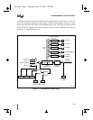
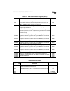
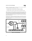
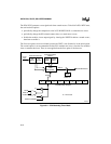
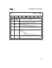
To program module 4 for the PCA WDT mode (Figure 9-4), set the ECOM4 and MAT4 bits in
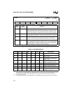
the CCAPM4 register and the WDTE bit in the CMOD register. Table 9-3 lists the bit combina-
tions for selecting module modes. Also select the desired input for the PCA timer/counter by pro-
gramming the CPS0 and CPS1 bits in the CMOD register (see Figure 9-7 on page 9-13). Enter a
16-bit comparison value in the compare/capture registers (CCAP4H/CCAP4L). Enter a 16-bit
initial value in the PCA timer/counter (CH/CL) or use the reset value (0000H). The difference
between these values multiplied by the PCA input pulse rate determines the running time to “ex-
piration.” Set the timer/counter run control bit (CR in the CCON register) to start the PCA WDT.