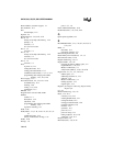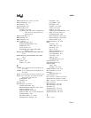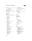
8XC251SA, SB, SP, SQ USER’S MANUAL
Index-6
Phone numbers, customer support, 1-7
Pin conditions, 12-3
Pins
unused inputs, 11-2
Pipeline, 2-5
POP instruction, 3-15, 5-10, A-22
Port 0, 7-2
and top of on-chip code memory, 14-2
pullups, 7-8
structure, 7-3
See also External bus
Port 1, 7-2
structure, 7-3
Port 2, 7-2
and top of on-chip code memory, 14-2
structure, 7-4
See also External bus
Port 3, 7-2
structure, 7-3
Ports
at power on, 11-7
exiting idle mode, 12-5
exiting powerdown mode, 12-5
extended execution times, 5-1, A-1, A-11
programming and verifying nonvolatile
memory, 14-3, 14-5, 14-6
Power supply, 11-2
Powerdown mode, 2-4, 12-1, 12-5–12-6
accidental entry, 12-4
entering, 12-6
exiting, 11-6, 12-6
external bus, 13-3
PROG#, 14-1
Program status word See PSW, PSW1
PSEN#
caution, 11-7
description, 13-2
idle mode, 12-4
programming and verifying nonvolatile
memory, 14-3
regions for asserting, 4-9
PSW, A-26
PSW, PSW1, 3-17, 3-18, 5-16–5-17, C-2, C-3, C-
21
conditional jumps, 5-14
effects of instructions on flags, 5-17
PSW1, A-26
Pullups, 7-8
ports 1, 2, 3, 7-6
Pulse width measurements, 8-10
PUSH instruction, 3-15, 5-10, A-22
Q
Quick-pulse algorithm, 14-1
R
RCAP2H, RCAP2L, 3-17, 3-19, 8-2, 10-12, C-2,
C-4, C-21
RD#, 7-1
described, 13-2
regions for asserting, 4-9
RD1:0 configuration bits, 4-9
Read-modify-write instructions, 7-2, 7-5
Real-time wait states, 13-10
Register addressing, 5-4, 5-5
Register banks, 3-2, 3-12
accessing in memory address space, 5-4
implementation, 3-12, 3-13
MCS 51 architecture, 3-3
selection bits (RS1:0), 5-18, 5-19, C-20
Register file, 2-5, 3-1, 3-5, 3-10–3-15
address space, 3-2
addressing locations in, 3-13
and reset, 11-6
MCS 51 architecture, 3-4
naming registers, 3-13
register types, 3-13
Registers, See Register addressing, Register banks,
Register file
rel, A-3
Relative addressing, 5-4, 5-13
Reset, 11-5–11-8
cold start, 11-6, 12-1
entering ONCE mode, 12-7
exiting idle mode, 12-5
exiting powerdown mode, 12-6
externally initiated, 11-6
need for, 11-7
operation, 11-6
power on, 11-7
power-on setup, 11-1
timing sequence, 11-6, 11-8
warm start, 11-6, 12-1
Response time, 6-9
RET instruction, 5-15, A-24


