


8XC251SA, SB, SP, SQ USER’S MANUAL
5-18
.
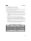
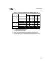
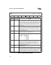
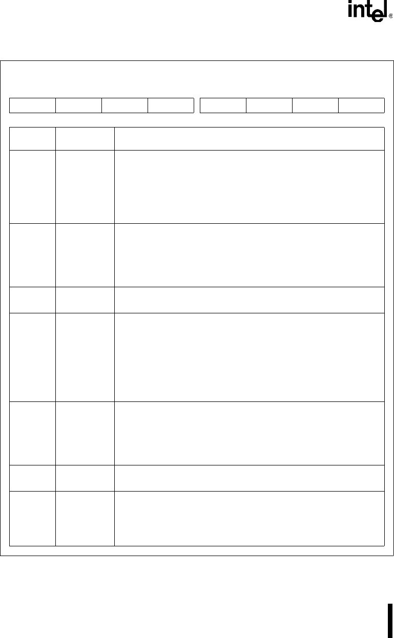
Figure 5-2. Program Status Word Register
PSW
Address: S:D0H
Reset State: 0000 0000B
7 0
CY AC F0 RS1 RS0 OV UD P
Bit
Number
Bit
Mnemonic
Function
7 CY Carry Flag:
The carry flag is set by an addition instruction (ADD, ADDC) if there is a
carry out of the MSB. It is set by a subtraction (SUB, SUBB) or compare
(CMP) if a borrow is needed for the MSB. The carry flag is also affected
by some rotate and shift instructions, logical bit instructions, bit move
instructions, and the multiply (MUL) and decimal adjust (DA) instructions
(see Table 5-10).
6 AC Auxiliary Carry Flag:
The auxiliary carry flag is affected only by instructions that address 8-bit
operands. The AC flag is set if an arithmetic instruction with an 8-bit
operand produces a carry out of bit 3 (from addition) or a borrow into bit
3 (from subtraction). Otherwise, it is cleared. This flag is useful for BCD
arithmetic (see Table 5-10).
5 F0 Flag 0:
This general-purpose flag is available to the user.
4:3 RS1:0 Register Bank Select Bits 1 and 0:
These bits select the memory locations that comprise the active bank of
the register file (registers R0–R7).
RS1 RS0 Bank Address
0 0 0 00H–07H
0 1 1 08H–0FH
1 0 2 10H–17H
1 1 3 18H–1FH
2 OV Overflow Flag:
This bit is set if an addition or subtraction of signed variables results in
an overflow error (i.e., if the magnitude of the sum or difference is too
great for the seven LSBs in 2’s-complement representation). The
overflow flag is also set if a multiplication product overflows one byte or if
a division by zero is attempted.
1 UD User-definable Flag:
This general-purpose flag is available to the user.
0 P Parity Bit:
This bit indicates the parity of the accumulator. It is set if an odd number
of bits in the accumulator are set. Otherwise, it is cleared. Not all instruc-
tions update the parity bit. The parity bit is set or cleared by instructions
that change the contents of the accumulator (ACC, Register R11).