


8XC251SA, SB, SP, SQ USER’S MANUAL
9-12
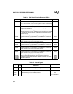
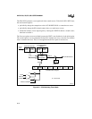
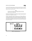
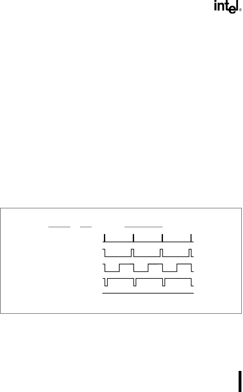
The value in CCAPxL determines the duty cycle of the current period. The value in CCAPxH de-
termines the duty cycle of the following period. Changing the value in CCAPxL over time mod-
ulates the pulse width. As depicted in Figure 9-6, the 8-bit value in CCAPxL can vary from 0
(100% duty cycle) to 255 (0.4% duty cycle).
NOTE
To change the value in CCAPxL without glitches, write the new value to the
high byte register (CCAPxH). This value is shifted by hardware into CCAPxL
when CL rolls over from FFH to 00H.
The frequency of the PWM output equals the frequency of the PCA timer/counter input signal
divided by 256. The highest frequency occurs when the F
OSC
/4 input is selected for the PCA tim-
er/counter. For F
OSC
= 16 MHz, this is 15.6 KHz.
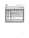
To program a compare/capture module for the PWM mode, set the ECOMx and PWMx bits in
the module’s CCAPMx register. Table 9-3 lists the bit combinations for selecting module modes.
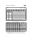
Also select the desired input for the PCA timer/counter by programming the CPS0 and CPS1 bits
in the CMOD register (see Figure 9-7). Enter an 8-bit value in CCAPxL to specify the duty cycle
of the first period of the PWM output waveform. Enter an 8-bit value in CCAPxH to specify the
duty cycle of the second period. Set the timer/counter run control bit (CR in the CCON register)
to start the PCA timer/counter.
Figure 9-6. PWM Variable Duty Cycle
A4161-01
Duty
Cycle
CCAP
x
L
255
230
128
25
0
0.4%
10%
50%
90%
100%
1
0
1
0
1
0
1
0
Output Waveform
1
0