


Instruction Manual
245364-V
May 2002
Rosemount Analytical Inc. A Division of Emerson Process Management Appendix A – Vaisala Pressure Transducer A-1
Model 755A
APPENDIX A
VAISALA BAROMETRIC PRESSURE TRANSDUCER
A-1 OVERVIEW
This is applicable if your instrument has a
Vaisala Barometric Pressure Transducer
installed in it, or, if you are retrofitting a 755A
with a Vaisala transducer kit.
The Vaisala PTB100 series Analog Barometer
is a N.I.S.T. traceable precision silicon
capacitive atmospheric pressure transducer.
The sensor delivers an analog voltage output
that is inversely proportional to it’s inlet
pressure. It has an operational ambient
pressure range of 800 to 1060 hPa.
The original 755A instrument was designed
for use with a resistance bridge type of
pressure transducer requiring an external
amplifier with a gain factor of 334. The
Vaisala transducer contains an integral gain
amplifier that is scaled for a 0 to +5 Vdc
output. The 755A “Door Board” can
accommodate either transducer type with a
single (R97) resistor change.
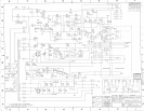
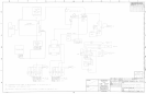
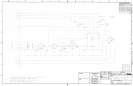
A-2 CIRCUIT FUNCTION
The 755A “Door Board” pressure transducer
interface is configured as a Precision Voltage
referenced “Whetstone Bridge” circuit. The
Vaisala Interface Circuit board adapts the
single ended analog output of the Vaisala
sensor into a Precision Voltage referenced,
balanced bridge (at 1 atmosphere) input
configuration. A “Bridge Balance” pot on the
Vaisala Interface Circuit board provides the
fine trim “Bridge Balancing” calibration
adjustment that is required to set up each
individual transducer at a known ambient air
pressure. Test points are provided on the
circuit board for this adjustment.
An adjustable, precision regulated voltage
divider consisting of R1, R2, & VR1 on the
Interface Board provide a bridge offset voltage
range of + 0.26 to + 0.79 Vdc.
The Vaisala transducer output range is 0 to
+5 Vdc.
The Vaisala analog output voltage is fed into a
voltage divider formed by R3 and R4 on the
Interface Board. This divider reduces the
Vaisala 0 to +5 Vdc output to 0 to +0.568
Volts, a reduction factor of 8.8 to 1.
These voltage divided bridge offset and
output signals are then applied to the original
Whetstone Bridge input circuit at connector J3
on the Door Board.
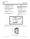
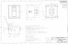
A-3 INSTALLATION
1. Remove the original transducer, located inside
the detector housing (if present).
2. Install the transducer using the mounting bracket
provided into the lower right hand corner of the
instrument.
3. Install the Interface board using the extended
mounting screw and spacer (provided) to the
top, left corner of the door board.
4. Connect the 4-pin cable (P1) from the interface
board (noting pin polarity) to J3 on the door
board.
5. Solder the Interface board WHITE wire to door
board J4-10 (+15 Vdc), and the BLACK wire to
J4-14 (Gnd).
6. Replace R97 on the door board with a 2 Meg
Ohm, 1/4W, 1% resistor (provided).