


Instruction Manual
245364-V
May 2002
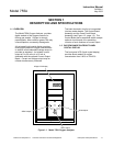
1-2 Description and Specifications Rosemount Analytical Inc. A Division of Emerson Process Management
Model 755A
1-3 OXYGEN RANGES FOR RECORDER
READOUT
If desired, the recorder output may be set for
a fullscale range of 0 to 100% oxygen.
Alternatively, a desired portion of this overall
range may be selected for fullscale
presentation on the recorder. The selection is
made by an appropriate combination of scale
expansion and zero suppression.
Scale Expansion
Fullscale oxygen span for the recorder is
switch selectable for 1%, 2%, 5%, 10%, 20%,
or 100% oxygen.
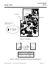
Zero Suppression
The desired zero suppression is obtained as
the sum of (a) a jumper selectable fixed value
of 0%, 20%, 40%, 60% or 80% oxygen and
(b) a continuously adjustable value of 0% to
25% oxygen. Thus the electronic circuitry
provides the capability of setting the total zero
suppression for any desired value from 0% up
to a theoretical maximum of 105% oxygen.
However, the maximum usable zero
suppression is 99%, which is used in
establishing a range of 99% to 100%.
The effective zero suppression, in volts, may
be read on the digital display by placing the
front panel TEST Switch in position 4 and the
Reorder Oxygen Span Selection Switch in 1 X
gain position (i.e., 100% oxygen)
Example:
Desired oxygen range for recorder output:
99% to 100% oxygen.
Required span is 1% oxygen, obtained by
jumper position.
Required zero suppression is 99% oxygen.
Thus, fixed zero suppression of 80% oxygen
is selected by jumper position, and adjustable
zero suppression is set for 19% oxygen.
1-4 RECORDER VOLTAGE AND CURRENT
OUTPUTS
Voltage Outputs (Standard)
Provided a standard is a jumper selectable
voltage output of 0 to 10 mV, 0 to 100 mV, 0
to 1 V, or 0 to 5 V DC.
Isolated Current Output (Option)
An isolated current output is obtainable with
the optional Current Output Board, either
included with the Model 755A or added at a
later date in the field.
This option provides a current output of either 0 to
20mA or 4 to 20mA for a maximum of 850 ohms.
Refer to Section 8 Replacement Parts, for the
part number of the Isolated Current Output
option.
NOTE
Voltage and current outputs may be used
simultaneously, if desired.
1-5 AUTOMATIC PRESSURE COMPENSATION
The oxygen readout is automatically corrected for
pressure variations within 3% of the target value,
which may be set anywhere within the range of -
2.7 to 3.3 psig ±3 psig (-18.6 to 22.8 kPa ±21 kPa.
1-6 OPTIONS
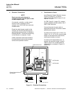
a. Alarm
The analyzer has an alarm relay assembly
consisting of two single-pole, double-throw
relays, one each for the ALARM 1 and
ALARM 2 contacts. These relays may be
used to drive external, customer-supplied
alarm and/or control devices.
b. Case Mounting
The analyzer is supplied, as ordered, with
hardware for one of three mounting
arrangements: Panel, wall, or pipe stanchion.
c. Electrical Power
The analyzer is supplied, as ordered, for
operation on either 120 VAC, 50/60 Hz, or
240 VAC, 50/60 Hz.