


Instruction Manual
245364-V
May 2002
Rosemount Analytical Inc. A Division of Emerson Process Management Theory 4-7
Model 755A
where
Vo = the corrected output signal
Vx = the amplified detector-output
signal, which includes a pressure
factor
Vz = the pressure signal derived
from: (a) The pressure sensor and
associated amplifiers, and (b) the
positive reference voltage power
supply
k = the constant that is characteristic
of the circuit
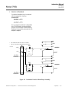
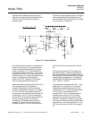
Amplifier U8
This amplifier works in conjunction with
analog divider U6, providing conditioned
output signal Vo as described in
Pressure Compensation Circuit above.
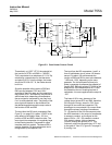
Amplifier U10
U10 is an non-inverting buffer amplifier
that incorporates an anticipation
arrangement in its input network, thus
providing slightly faster response time
(90% of fullscale on the readout device(s).
Potentiometer R30 provides a
continuously variable adjustment of 5 to
25 seconds for the electronic anticipation
time and is factory-set for 20 seconds.
Since the anticipation network attenuates
the signal, a gain of 10 is provided in U10
to restore the signal to the desired
fullscale range of 0 to 10 VDC.
The pressure-corrected signal from U10 is
routed to two output circuit:
Digital Output Circuit. The signal from
U10 passes through TEST switch SW1
and a filter circuit to an integrating analog-
to-digital converter. The resulting digital
signal drives the liquid crystal display.
Analog Output Circuit . The output from
U10 is provided as an input to the
recorder output amplifier. This circuitry
provides zero suppression, scale
expansion, and amplification preparatory
to use for potentiometric recorder,
voltage-to-current conversion for current
recorder, and/or alarm functions.
Zero suppression is obtained as the sum
of (1) a jumper selectable, fixed value of
0%, 20%, 40%, 60%, or 80% and (2) a
continuously adjustable value of 0% to
25%.
The scale expansion factor is jumper
selectable for 1, 10, or 100.
Potentiometric output is jumper selectable
for 0 to 10mV, 0 to 100mV, 0 to 1V, or 0
to 5VDC.
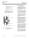
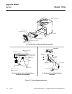
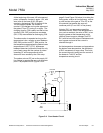
c. Case Board
The Case Board contains power supply
and temperature control circuits. The
board is mounted inside of the analyzer
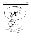
case (see Figure 1-2 on page 1-3).
The various circuits operate on main
power transformer T1. The two primary
windings of T1 are configured (at the
factory) for operation on either 120 VAC
or 220 VAC.
The Case Board consists of the following:
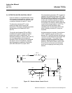
Source Lamp Power Supply
This circuit provides a regulated output of
2.30 VDC to operate incandescent source
lamp DS1 within the optical bench
assembly. One secondary of main power
transformer T1 drives a fullwave rectifier
consisting of CR7 and CR8. The output
of DS1 is held constant by a voltage
regulator circuit utilizing U7, Q4, and Q5.
±15V Power Supply
This circuit provides DC voltages
required for various amplifiers and other
circuits. Fullwave rectifier bridge CR5
provides both positive and negative
outputs. Each is routed through an
associated series-type integrated circuit