


Instruction Manual
245364-V
May 2002
6-6 Service and Maintenance Rosemount Analytical Inc. A Division of Emerson Process Management
Model 755A
If the lamp assembly removed from the
instrument has four wires, the 633689
Connector Board requires modification.
Continue to step 10.
10. Refer to Figure 6-1 on page 6-4. Remove
the two screws holding the Connector
Board to the magnet assembly. Carefully
remove Connector Board.
11. Place Connector Board on a clean
working surface, with solder side (no
components) up.
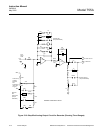
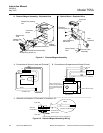
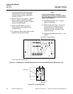
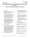
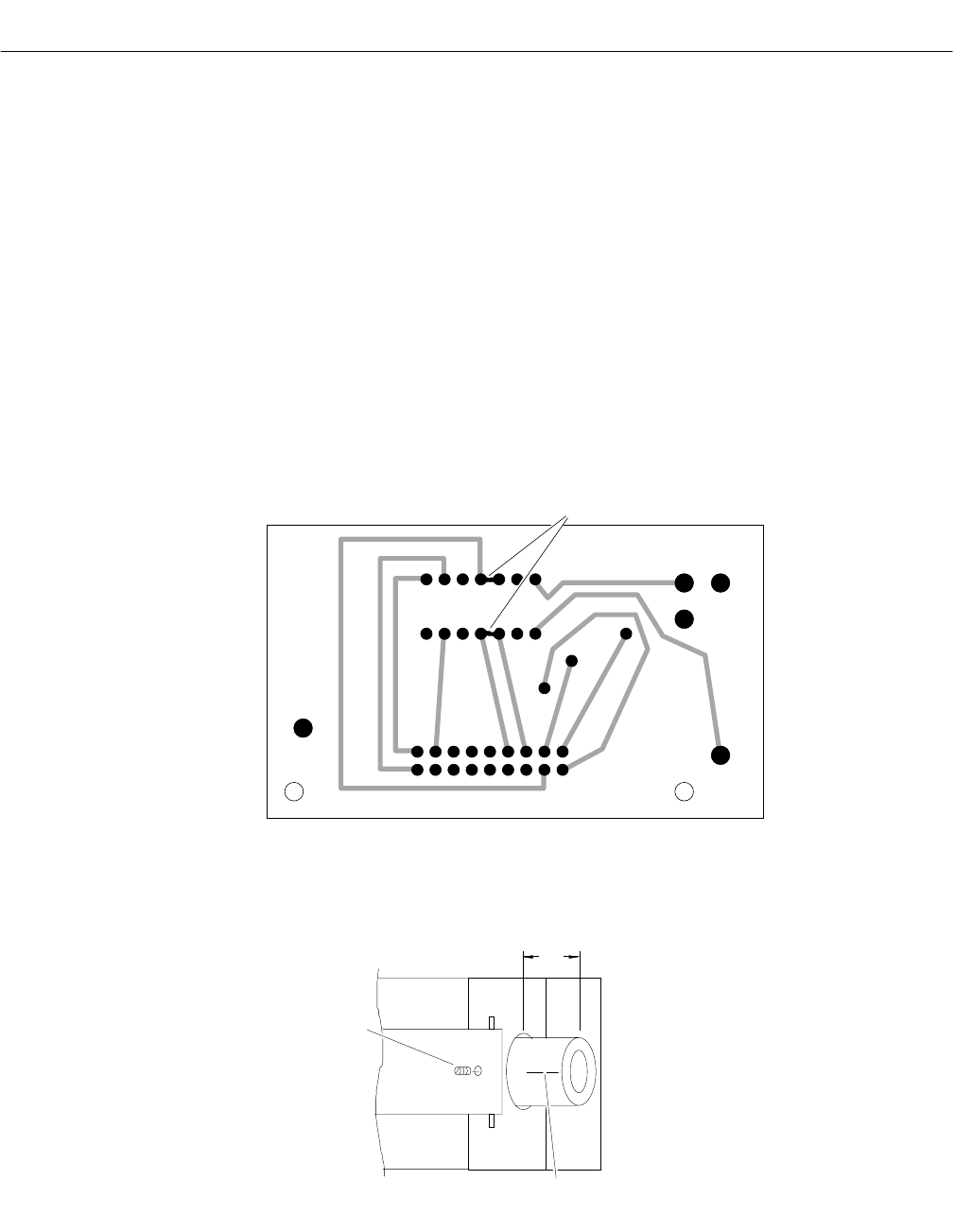
12. Per Figure 6-4 below, add straps or solder
bridges at the two points shown.
NOTE
If the Connector Board cannot be
satisfactorily modified, a modified 633689
Connector Board may be ordered from the
factory. See Section 7.
13. Reassemble detector, etc., in reverse
order of disassembly.
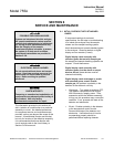
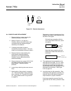
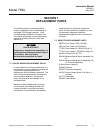
14. Refer to Figure 6-5 below. The red line
on the lamp must be aligned with the
retaining set screw. Insert lamp into
mounting hole until it extends 1/4 inch.
Tighten set screw.
15. Realign the photocell per Section 1-1a on
page 6-7.
Figure 6-4. Modification of 633689 Connector Board for Compatibility with Replacement Lamp
Figure 6-5. Lamp Alignment
1/4"
Red Mark for
Alignment
Set Screw
Solder Side of Board (Backside)
F3
HR1
Add Straps or Solder Bridges