


Instruction Manual
245364-V
May 2002
3-6 Operation Rosemount Analytical Inc. A Division of Emerson Process Management
Model 755A
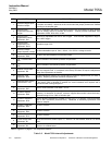
ITEM CONTROL DESCRIPTION
1
Recorder Oxygen Span
Selection Jumper
Provides selectable span of 100%, 20%, 10%, 5%, 2%, or 1% oxygen for analog output
to recorder and alarms. Note that on the circuit board the jumper positions are marked
according to the amplifier gain.
2
Recorder Zero
Suppression Selection
Jumper
Used in combination with item 3 to establish required zero suppression to obtain desired
range for analog output to recorder and alarms. Jumper provides selectable zero
suppression of 20%, 40%, 60%, or 80%
3
Recorder Zero
Suppression Coarse
Adjustment R41
Continuously adjustable from 0% to 25% oxygen. Thus the total suppression range is
0% to 105% oxygen.
4
Recorder Zero
Suppression Fine
Adjustment R104
Adjustable range of 2%.
5
Recorder Voltage
Output Selection Jumper
Provides selectable output of 10mV, 100mV, 1V or 5V for a voltage recorder.
6
Recorder Span
Adjustment R88
Provides ±5% span adjustment of recorder output.
7
CAL 1 Potentiometer
R98
Used in calibration of automatic pressure compensation.
8
CAL 2 Potentiometer
R99
Used in calibration of automatic pressure compensation.
9
Detector Coarse Zero
Adjustment R9
Provides coarse adjustment of detector zero by shifting the null position of the detector
within the magnetic field. It is adjusted at the factory and does not require readjustment
except after replacement of detector.
10
Response Time
Adjustment R30
Provides adjustment range of 5 to 25 seconds for electronic response time (0 to 90% of
fullscale). Adjusting clockwise decreases response time.
11
Response Ratio Timing
Potentiometer R29
Permits compensation for slight gain changes that may result from adjustment of R20.
At the factory, R29 is adjusted to establish the exact resistance ratio required and is
then secured with locking compound.
12
ALARM 2 Calibration
Adjustment R67
Used for initial calibration of ALARM 2 circuit.
13
ALARM 2 Setpoint
Adjustment R68
Provides continuously variable adjustment of setpoint for ALARM 2 circuit on alarm
accessory, for actuation of external, customer supplied alarm and/or control device(s).
Adjustment range is 0 to 100% of fullscale span.
14
ALARM 2 Deadband
Adjustment R78
Permits adjusting deadband of ALARM 2 circuit from 1% of fullscale (counterclockwise
limit) to 20% of fullscale (clockwise limit). Deadband is essentially symmetrical with
respect to setpoint.
15
ALARM 1 Calibration
Adjustment R63
See item 12 above.
16
ALARM 1 Setpoint
Adjustment R64
See item 13 above.
17
ALARM 1 Deadband
Adjustment R73
See item 14 above.
8
Current Output Zero
Adjustment R1
Use to set zero-level current output, i.e., 4mA for 4 to 20mA board, 0mA for 0 to 20mA
board.
19
Current Output Span
Adjustment R2
Use to set fullscale current output at 20mA for 4 to 20mA or 0 to 20mA board or at
50mA for 10 to 50mA board.
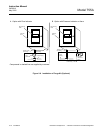
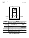
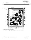
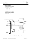
Refer to Figure 3-2, page 3-7, for component locations.
Table 3-2. Model 755A Internal Adjustments