


Instruction Manual
245364-V
May 2002
Rosemount Analytical Inc. A Division of Emerson Process Management Service and Maintenance 6-5
Model 755A
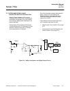
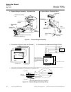
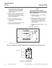
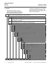
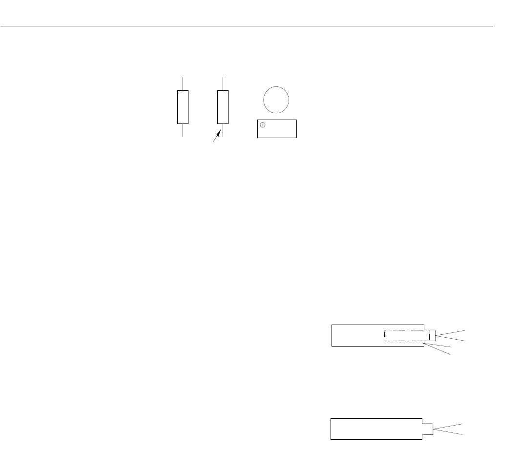
C1
R13
R9
U2
Voltmeter
Lead
Two Red or
Two Black Leads
Red
Blue
Brown
Yellow
Figure 6-3. Detector Adjustment
6-4 SOURCE LAMP REPLACEMENT
1. Remove the four screws securing the
detector assembly cover plate.
2. Refer to Figure 6-1 on page 6-4.
Carefully remove the small rubber hose
connected from the detector/magnet
assembly to the detector.
3. If retaining set screw for lamp is
accessible, proceed to step 6. If the set
screw is not accessible continue to step 4.
4. Remove the two screws holding the
optical bench assembly/detector
assembly to the magnet assembly.
Carefully remove optical bench and
detector assembly.
5. Remove the two lock screws (2-56 X 5/16
pan head) holding the photocell in the
optical bench. Carefully remove
photocell.
6. Loosen lamp retaining set screw, remove
lamp.
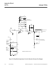
7. Note location of lamp wires in connector
J12. Disconnect leads of lamp assembly
from connector J12, Figure 6-2A on page
6-4, using method shown in Figure 6-2C
on page 6-4.
Depending on date of manufacture of the
analyzer, the original lamp assembly may
be either of two types:
Old style lamp assembly with four
color coded leads: Red, blue, brown
and yellow.
New style lamp assembly with two
leads color coded either both red or
both black.
8. The replacement lamp assembly is the
new style with two leads. On J12, insert
one lead into the position formerly used
for the brown lead to the old style lamp
and the other lead into the position for the
blue lead of the old lamp. See Figure
6-2A on page 6-4
9. Insert the lamp into the assembly. After
reassembly and application of power, the
lamp will have to be rotated to place the
lamp filaments in proper orientation.
If the lamp assembly removed from the
instrument has two wires, proceed to step
13.