


Instruction Manual
245364-V
May 2002
5-10 Circuit Analysis Rosemount Analytical Inc. A Division of Emerson Process Management
Model 755A
From Pressure
Signal Circuit
Figure 6-8
-
+
U8
FRONT
PANEL
SPAN
+15V
-15V
CR2
1000pf
C2
.01uF
R9
110
R6
2M
C3
.47uF
R7
118K
R8
1.69K
-
+
U1
C6
R18
24.9K
R19
10
DS1
BT1
BT2
FEEDBACK
LOOP
-
+
U4
R16
R5
R17
C1
.0022uF
30K
R44
200K
R9
20K
R13
20K
+15V
-15V
+15V
-15V
DETECTOR
COARSE
ZERO
FRONT
PANEL
ZERO
-
+
U2
U6
Vx
Vz
To Digital and
Analog Circuits
+10V
PRESS
SENSOR
-
+
U7
-10V
CAL 1
CAL2
-
+
U9
R98
R99
To Test
Switch
To Analog
Divider U6
Reference
Voltages
REFERENCE
+10.00V
Reference Voltage Circuit
R19
TRIM
U3
REFERENCE
-
+
U5
-10.00V
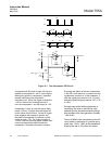
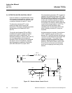
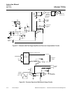
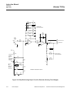
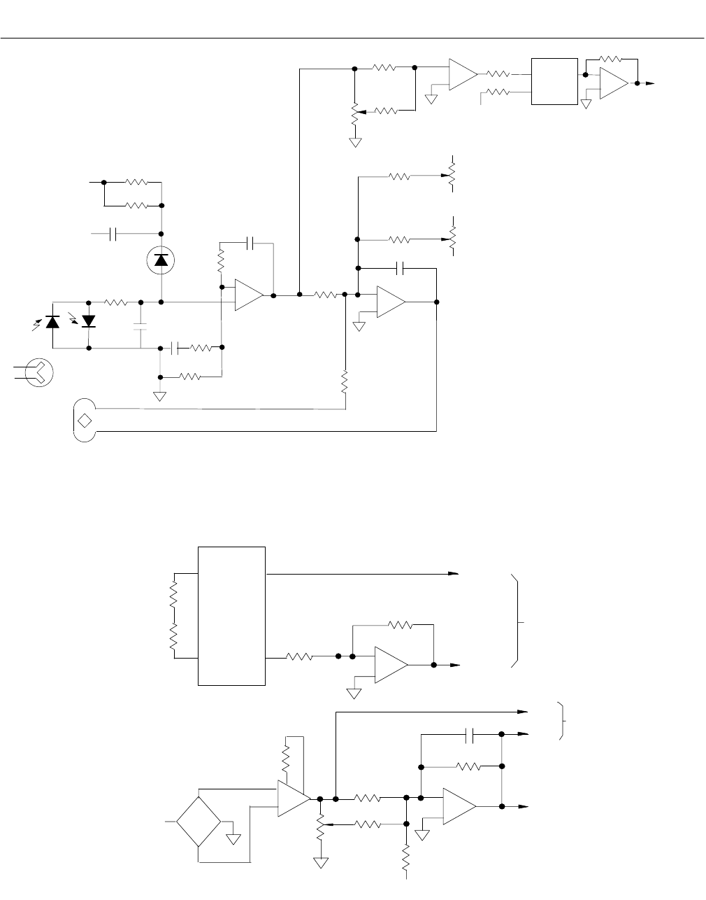
Figure 5-7. Detector with First Stage Amplifier and Pressure Compensation Circuits
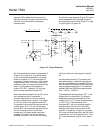
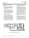
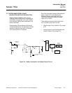
Figure 5-8. Pressure Signal and Reference Voltage Circuits