


Instruction Manual
245364-V
May 2002
4-2 Theory Rosemount Analytical Inc. A Division of Emerson Process Management
Model 755A
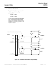
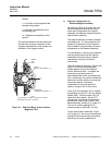
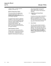
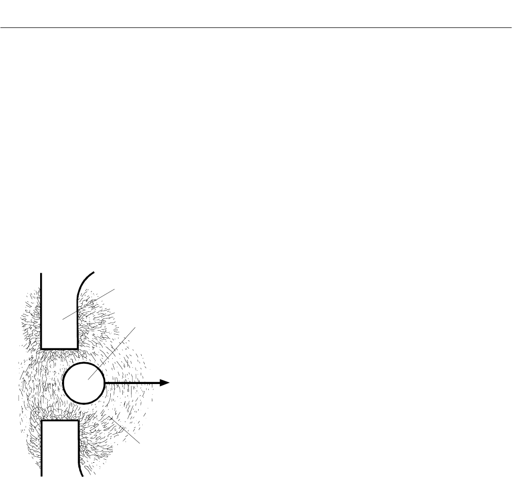
Shaded
Pole
Piece
Sphere
(Magnetic Susceptibility = k
o
)
F
k
Sample Gas
(Magnetic Susceptibility = k
)
Note:
As percentage of oxygen in sample gas increases,
displacement force (F
k
) increases.
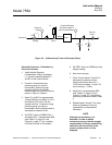
Where:
c = A function of the magnetic field
strength and gradient
k = Magnetic susceptibility of the
surrounding gas
k
o = Magnetic susceptibility of the
sphere
The forces exerted on the two spheres of
the test body are thus a measure of the
magnetic susceptibility of the sample and,
therefore, of its oxygen content.
Figure 4-1. Spherical Body in Non-Uniform
Magnetic Field
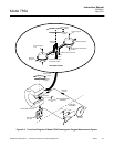
b. Physical Configuration of
Detector/Magnet Assembly
As shown in Figure 4-3A (page 4-4), the
Detector/Magnet Assembly consists of
three major components; the magnet
assembly, the detector assembly and the
optical bench assembly.
The magnet assembly includes a sample
pre-heating coil. It is connected into the
sample line upstream from the detector
and is heated to approximately the same
temperature as the detector assembly.
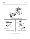
For convenience in servicing, the detector
and the optical bench are self-aligning
assemblies that utilize slip-on sample
connections and plug-in electrical
connections.
Within the detector assembly, Figure 4-3B
(page 4-4), the incoming preheated
sample passes through an integral 5
micron diffusion screen. It protects the
test body by preventing entry of
particulate matter and/or entrained liquid
mist. Additionally, the screen isolates the
test body from flow effects, ensuring that
instrument readout is relatively
independent of flow rate within the
optimum range of 200 to 300 cc/min.
At the rear of the detector are an integral
temperature sensor (RT1) and an integral
heater (HR2). Another heater (HR1) is
attached to the magnet. Sensor RT1
provides the input signal to the detector
temperature control circuit of the Case
Board assembly, Section 4-3c (page 4-7).
This circuit controls application of
electrical power to both HR1 and Hr2.
On the optical bench assembly, Figure
4-3C (page 4-4), the source lamp and the
photocell plate are externally accessible,
permitting convenient replacement.