


Instruction Manual
245364-V
May 2002
Rosemount Analytical Inc. A Division of Emerson Process Management Service and Maintenance 6-7
Model 755A
a. Photocell Replacement and
Adjustment
1. To remove the photocell from the
optical bench, perform steps 1
through 5 in Section 6-4 on page 6-5.
2. Install replacement photocell by
reversing removal procedure.
3. The photocell must now be adjusted.
With zero gas flowing:
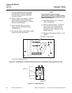
a. Place a digital voltmeter on the
wiper of the front panel ZERO
control (R13) and ground (TP7)
ground on the Control Board.
Adjust front panel ZERO control for
0.0 VDC.
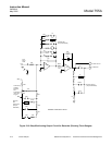
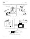
b. Place the voltmeter from the bottom
of R10 and TP7 (see Figure 6-5 on
page 6-6), adjust R9 for 0 VDC.
c. Place the voltmeter on TP8 and
TP7, move the photocell to obtain a
DC voltage as close to 0mV as
possible but not more than ±750mV.
d. Perform steps 8 through 11 in Section
6-3a on page 6-3.
With all internal adjustments now properly
set, the instrument may be calibrated in
the normal manner.
6-5 HEATING CIRCUITS
To ensure against damage from overheating
in the event of malfunction, the heating
circuits are protected by thermal fuses F2 and
F3. If temperature of a heated area exceeds
the permissible maximum, the associated fuse
melts, opening the circuit.
NOTE
Thermal fuses F2 and F3 are to be plugged
in, never soldered. If soldered, the fuse
element may melt and open the circuit.
a. Case Heater Control Circuit
The case heater control circuit receives
power via thermal fuse F2 (76°C). This
fuse, located on the Case Board, can be
checked for continuity.
Case heater element HR3, located on the
heater/fan assembly, has a normal
resistance of 20 ohms.
To verify heater operation, place a hand
beside the right-hand side of the detector
housing. Heated air should be felt. If it is
not, check the case heating circuit.
Temperature sensor RT1 has a cold
resistance of 22.7K ohms and a normal
operating resistance of 20.2K ohms,
indicating normal operating temperature
of 140°F (60°C). Until thyristor RV1
reaches operating temperature, it
bypasses most of the current that would
otherwise flow through Triac Q7.
As a further check, disconnect connector
plug P8 on the Control Board, thus
disconnecting temperature sensor RT1.
Substitute a decade resistor box to
simulate the resistance of RT1. Also,
connect an AC voltmeter from the hot side
of the line to the neutral side of F2.
Set the decade box for 20.2K ohms to
simulate RT1 resistance at controlling
temperature. The voltmeter should now
show pulses of 1 VAC.
CAUTION
OVERHEATING HAZARD
Avoid prolonged operation with the
decade box set at 22.2K ohms.
Overheating may result.
Set the decade box for 22.2K ohms to
simulate RT1 resistance at ambient
temperature. The voltmeter should now
show pulses of 120 VAC.