


Instruction Manual
245364-V
May 2002
Rosemount Analytical Inc. A Division of Emerson Process Management Circuit Analysis 5-1
Model 755A
SECTION 5
CIRCUIT ANALYSIS
5-1 OVERVIEW
The electronic circuitry of the Model 755A
Oxygen Analyzer consists of the following:
•
A detector compartment heater circuit.
•
A detector heater circuit.
•
A ±15VDC power supply.
•
A voltage regulating circuit for a stable
light source.
•
A detector circuit with a first-stage
amplifier to provide a feedback current for
mechanical feedback to the detector and
a scaling amplifier circuit to give an output
change of 0 to +2.5V for a 0 to 100%
change of the operating span.
•
A digital output circuit for the digital read-
out.
•
An analog output circuit for recorder,
optional alarms and current output.
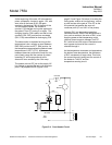
5-2 ±15VDC POWER SUPPLY
The components of the ±VDC power supply
circuit are located in the lower left-hand corner
of the Case Board. 19VAC should be
measured with respect to ground at CR5
(WO4). +15VDC should be measured at the
C27 (+) lead and -15VDC at the C28 (-) lead.
If the specified voltage measurements are
obtained, the power supply is working
correctly.
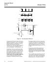
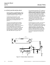
5-3 CASE HEATER CONTROL CIRCUIT
The case heater control circuit utilizes four
voltage-comparators (LM339 quad com-
parator). An understanding of how one of
these comparators functions is necessary
before any circuit analysis can be attempted.
In Figure 5-1 on page 5-2, comparators 1 and
2 are depicted having a comparator within an
overall comparator symbol. Also within this
symbol, the base of the NPN transistor is
connected to the output of the comparator.
-15VDC is supplied to the emitter. The
collector is illustrated as the overall output for
the comparator package.
The use of a transistor, built into the output of
the comparator, allows comparators to be
placed together in an OR circuit.
Comparators 1 and 2 (in Figure 5-1 on page
5-2) illustrate this logic principle.
When the non-inverting terminal of
comparator 2 is more positive than the
inverting terminal, the transistor does not
conduct and the collector of the transistor or
comparator output is at whatever potential is
then present on the collector.
When the non-inverting terminal of
comparator 2 is less positive (more negative)
than the inverting terminal, the transistor
conducts and the output of the comparator is
-15V. This value is the output of the OR
circuit.
Comparator 2 is biased at 0 volts on the
inverting terminal. Comparator 1 is biased at
about 159 mV on the non-inverting terminal.
Positive feedback or hysteresis is built into
each comparator circuit for stability or positive
action. This is achieved by the 20M ohm
resistances, R70 and R73.