


Instruction Manual
245364-V
May 2002
4-8 Theory Rosemount Analytical Inc. A Division of Emerson Process Management
Model 755A
voltage regulator, providing regulated
outputs of +15V and -15V.
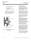
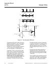
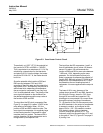
Detector Temperature Control
This circuit maintains the detector at a
controlled temperature of 150°F (66°C).
Temperature is sensed by RT1, a
resistance element permanently attached
to the detector assembly.
The signal from the sensors is applied to
amplifier U6, which drives transistors Q2
and Q3, thus controlling application of DC
power from fullwave rectifier bridge CR6
to the two heaters within the
detector/magnet assembly; HR1,
mounted on the top of the magnet, and
HR2, mounted permanently on the rear of
the detector assembly.
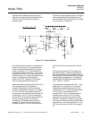
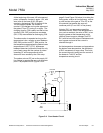
Case Temperature Control
This circuit maintains the interior of the
analyzer case at a controlled temperature
of 140°F (60°C). Temperature is sensed
by a thermistor on the Control Board
adjacent to critical electronic components.
The circuit provides on-off control of
heater element HR3 via TRIAC Q7.
Heater HR3 is located in the heater/fan
assembly.
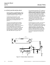
d. Isolated Current Output Board
(Optional)
An isolated current output is obtainable by
insertion of an optional plug-in circuit
board into receptacle J1 on the Control
Board assembly (See Figure 1-2 on page
1-3). The current outputs available by this
board are 0 to 20 mA or 4 to 20 mA.
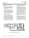
e. Alarm Option
The alarm option provides two sets of
relay contacts for actuation of (customer-
supplied) alarm and/or process control
device(s). The alarm relay assembly has
two single-pole, double-throw relays, one
each for the ALARM 1 and ALARM 2
contacts. Alarm output connections are
on the terminal board shown in Figure 2-1
on page 2-2.