


Instruction Manual
245364-V
May 2002
5-8 Circuit Analysis Rosemount Analytical Inc. A Division of Emerson Process Management
Model 755A
5-6 DETECTOR WITH FIRST STAGE AMPLIFIER
AND PRESSURE COMPENSATION
CIRCUITS
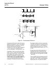
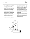
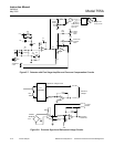
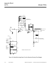
Refer to Figure 5-7 on page 5-10. The
detector assembly consists of a test body
suspended on a platinum wire and located in
a non-uniform magnetic field.
The test body is constructed of two hollow
glass spheres forming a dumbbell shape.
They are filled and sealed with pure, dry
nitrogen. Around the test body, a titanium wire
is chemically etched in order to form a
feedback loop that can create a counteracting
magnetic force to the test body displacement
caused by oxygen concentration in the test
assembly magnetic field.
Attached to the center arm of the test body
dumbbell is a diamond-shaped mirror.
Attached to the mirror are two separate
platinum wires in tension with the supports for
the test body. The supports are isolated from
ground and are electrically connected to the
feedback loop and the electronics for that
loop. The platinum wires form a fulcrum
around which the test body pivots.
The detector operates in the following fashion.
If the sample gas contains oxygen, it collects
in the non-uniform magnetic field around the
test body. Oxygen, because of its
paramagnetic qualities, gathers along the
magnetic lines of flux and forces the dumbbell
of the test body out of the magnetic field.
A light source is focused on the test body
mirror. As the test body moves out of the
magnetic field, the mirror distributes light
unevenly on two photocells (BT1 and BT2).
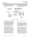
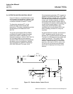
The photocells create a potential at
comparator U1. The output of U1 goes to U2.
The output of U2 causes current to flow
through the feedback loop attached to the
dumbbell and mirror into the test assembly
magnetic field until the mirror reflects light
almost uniformly on each photocell. A current
proportional to the oxygen concentration in
the magnetic field of the test assembly has to
be flowing through the feedback loop in order
to maintain balance and provide a reading of
the oxygen content of the sample.
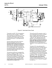
Resistances R5, R17 and the resistance of
the wire in the feedback loop determine the
gain of amplifier AR2. The mirror on the
dumbbell is positioned by the amount of
current in the feedback loop. The mirror
reflects light from the source (DS1) to the
photocells (BT1, BT2). This repositioning of
the mirror is a form of mechanical feedback to
the input of the amplifier U1. The net result is
that the output of U1 could vary from 0 to -70
mV, or 0 to -7.0V, depending on the range of
the instrument
On application of AC power, capacitor C6 has
no charge. The current will have to flow
through R18. Initially the full 30V drop (the
difference between the ±15VDC power) will
appear cross R18. The cathode of CR2 will be
initially at -15VDC. The anode of CR2 will be
some value more positive than -15VDC. CR2
will conduct. The input terminal of U1 will be
negative and the current through the feedback
loop around U2 will cause the dumbbell and
mirror to be positioned correctly in the test
body.
As the charge on C6 increases, the cathode
of CR2 becomes more positive. When it
exceeds that on the anode, CR2 ceases to
conduct and isolates the ±15VDC power
supply from the input circuit.
Coarse Zero Adjust R9 and front panel ZERO
potentiometer R13 permit adding an
appropriate voltage to the input of U2 to
counteract any electrical offset resulting from
imbalance in the detector and/or photocells
BT1 and BT2.
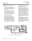
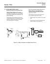
The output current that U2 must provide to
restore the dumbbell is a measure of the
displacing force and thus is a function of both
(a) the % oxygen concentration of the sample
and (b) the sample pressure.
The output from U2 is further amplified by U4
to provide a 0 to 10VDC output that
constitutes signal Vx for the pressure
compensation circuit described in Section 5-
6a on page 5-9 .