


Instruction Manual
245364-V
May 2002
Rosemount Analytical Inc. A Division of Emerson Process Management Description and Specifications 1-3
Model 755A
+
-
+
COM
MA
MV
TB2
NO
COM
NC
RESE
NO
CO
NC
RESET
NO. 1
NO. 2
HOT
GND
N
E
U
T
H
O
T
TB1
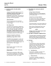
Zero Suppression
Adjustment
CAL2 Adjustment,
Pressure Compensation
CAL1 Adjustment,
Pressure Compensation
Location for Optional Current
Output Board
Control Board
ZERO Control
SPAN Control
Span -
Jumper Select
Recorder Output -
Jumper Select
Zero Offset -
Jumper Select
Recorder Output
TB2
Case Board
Transformer, Power T1
(Behind TB1)
Alarm Relay Assembly
(Alarm Option)
Case Heater
Assembly
AC Power
TB1
Detector/Magnet
Assembly
Detector/Magnet As-
sembly Shock
Mount
Fuse
AC Power
Fuse
Case Heater
Transducer
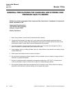
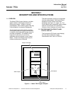
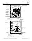
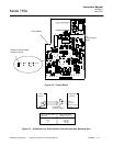
Figure 1-2. Model 755A Component and Adjustment Locations