


Instruction Manual
245364-V
May 2002
6-8 Service and Maintenance Rosemount Analytical Inc. A Division of Emerson Process Management
Model 755A
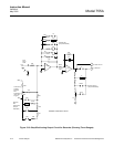
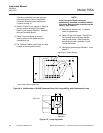
b. Detector/Magnet Heating Circuit
Heater HR1 is attached to the magnet.
Heater HR2 is attached to the rear of the
detector. Combined resistance of these
two parallel connected heaters, as
measured at pins 15 and 16 of detector
connector J12, should be approximately
17 ohms. If not, remove pin/leads 14 and
15 from the connector to measure the
resistance of HR2 alone. This resistance
should be approximately 89 ohms.
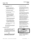
If resistance the resistance of HR2 is
correct, and yet the combined resistance
is incorrect, heater HR1 may be open.
To reach the leads of HR1, remove the
printed circuit board on the heater
assembly. Resistance of HR1 should be
approximately 21 ohms.
To check operation of the heater circuit,
connect a voltmeter across R61 on the
Case Board. Normally, the voltage will be
4 VDC when cold and will drop to
approximately 0.4 VDC at control
temperature. Temperature sensor RT1 is
mounted in the detector, with leads
accessible at pins 10 and 11 of detector
connector J12. The sensor resistance, as
measured at these pins, should be 1M
ohm at 25°C and approximately 149K
ohms at operating temperature of 65°C.