


Instruction Manual
245364-V
May 2002
Rosemount Analytical Inc. A Division of Emerson Process Management Theory 4-5
Model 755A
4-2 VARIABLES INFLUENCING
PARAMAGNETIC OXYGEN
MEASUREMENTS
Variables that influence paramagnetic oxygen
measurements include: operating pressure,
Section 4-2a below; sample temperature,
Section 4-2b below; interfering sample
components, Section 4-2c (page 4-5); and
vibration 4-2d (page 4-5).
a. Pressure Effects
Although normally calibrated for readout
in percent oxygen, the Model 755A
actually responds to oxygen partial
pressure. The partial pressure of the
oxygen component in a gas mixture is
proportional to the total pressure of the
mixture. Thus readout is affected by
pressure variations. However, the
instrument incorporates electronic
circuitry that provides automatic pressure
compensation for pressure variations
within ±3% of the target value, which may
be set anywhere in the range of -2.7 to
3.3 psig ±3 psig (-18.6 to 22.8 kPa ±21
kPa).
WARNING
POSSIBLE EXPLOSION HAZARD
Never subject the sensing unit to an
absolute pressure of less than 500 mm Hg
(66.7 kPa).
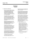
b. Temperature Effects
Magnetic susceptibilities and partial
pressures of gases vary with temperature.
In the Model 755A, temperature-induced
readout error is avoided by control of
temperatures in the following areas:
1. Interior of the analyzer case is
maintained at 140°F (60°C) by an
electronically controlled heater and
associated fan.
2. Immediately downstream from the
inlet port, prior to entry into the
detector, the sample is preheated by
passing through a coil maintained at
approximately the same temperature
as the detector.
3. The detector is maintained at a
controlled temperature of 150°F
(66°C).
c. Interferents
Instrument response to most non-oxygen
sample components is comparatively
slight but is not, in all cases, negligible.
Table 3-3 (page 3-11) lists the readings
that would be obtained with various gases
on an instrument previously calibrated
with 100% oxygen, assuming that all
gases are admitted at the same pressure.
During initial installation of an instrument
for a given application, effects of the
background gas should be calculated to
determine if correction is required. See
Section 3-5c, page 3-10.
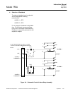
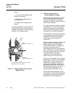
d. Vibration Effects
Instrument Design
To minimize vibration effects, the
detector/magnet assembly is contained in
a shock-mounted compartment, Figure
1-2 (page 1-3).
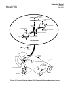
Installation
Avoid excessive vibration. In making
electrical connections, do not allow any
cable to touch the shock-mounted
detector/magnet assembly or the
associated internal sample inlet and outlet
tubing. This precaution ensures against
possible transmission of mechanical
vibration through the cable to the
detector, which would cause noisy
readout.
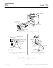
Electronic Response Time
If readout is noisy despite precautions
mentioned above, obtain slower electronic
response by counterclockwise adjustment
of Response Time Adjust R30 (see Table
3-2, page 3-6, and Figure 3-2, page 3-7).