


Instruction Manual
245364-V
May 2002
iv Contents Rosemount Analytical Inc. A Division of Emerson Process Management
Model 755A
LIST OF ILLUSTRATIONS
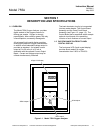
Figure 1-1. Model 755A Oxygen Analyzer ............................................................................... 1-1
Figure 1-2. Model 755A Component and Adjustment Locations ............................................. 1-3
Figure 2-1. Electrical Connections ........................................................................................... 2-2
Figure 2-2. Control Board......................................................................................................... 2-3
Figure 2-3. Connections for Potentiometric Recorder with Non-Standard Span ..................... 2-3
Figure 2-4. Model 755A Connected to Drive Several Current-Activated Output Devices ....... 2-4
Figure 2-5. Typical Alarm Settings........................................................................................... 2-6
Figure 2-6. Relay Terminal Connections for Typical Fail-Safe Application.............................. 2-6
Figure 2-7. Connection of Typical Gas Selector Panel to Model 755A Oxygen Analyzer....... 2-8
Figure 2-8. Installation of Purge Kit (Optional)....................................................................... 2-12
Figure 3-1. Model 755A Front Panel Controls ......................................................................... 3-2
Figure 3-2. Model 755A Internal Adjustments Locations ......................................................... 3-7
Figure 3-3. Calibration by Pressure Decrease Setup .............................................................. 3-9
Figure 3-4. Schematic Circuit of Alarm Relay Assembly ....................................................... 3-13
Figure 4-1. Spherical Body in Non-Uniform Magnetic Field..................................................... 4-2
Figure 4-2. Functional Diagram of Model 755A Paramagnetic Oxygen Measurement
System................................................................................................................... 4-3
Figure 4-3. Detector/Magnet Assembly.................................................................................... 4-4
Figure 5-1. Two-Comparator OR Circuit .................................................................................. 5-2
Figure 5-2. Ramp Generator.................................................................................................... 5-3
Figure 5-3. Case Heater Control Circuit................................................................................... 5-4
Figure 5-4. Case Heater Circuit ............................................................................................... 5-5
Figure 5-5. Detector Heater Control Circuit.............................................................................. 5-6
Figure 5-6. Detector Light Source Control Circuit .................................................................... 5-7
Figure 5-7. Detector with First Stage Amplifier and Pressure Compensation Circuits .......... 5-10
Figure 5-8. Pressure Signal and Reference Voltage Circuits ................................................ 5-10
Figure 5-9. Buffer, Anticipation, and Digital Output Circuit .................................................... 5-11
Figure 5-10. Simplified Analog Output Circuit for Recorder (Showing Three Ranges) ........... 5-14
Figure 6-1. Detector/Magnet Assembly.................................................................................... 6-4
Figure 6-2. Detector/Magnet Assembly Wiring ........................................................................ 6-4
Figure 6-3. Detector Adjustment .............................................................................................. 6-5
Figure 6-4. Modification of 633689 Connector Board for Compatibility with Replacement
Lamp...................................................................................................................... 6-6
Figure 6-5. Lamp Alignment..................................................................................................... 6-6
LIST OF TABLES
Table 3-1. Standard Gases Recommended for Calibration of Various Oxygen Ranges on
Analog Output........................................................................................................ 3-5
Table 3-2. Model 755A Internal Adjustments.......................................................................... 3-6
Table 3-3. Oxygen Equivalents of Common Gases.............................................................. 3-11