


Instruction Manual
245364-V
May 2002
Rosemount Analytical Inc. A Division of Emerson Process Management Installation 2-9
Model 755A
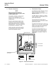
c. Normal Operation at Positive Gauge
Pressures
Pressure at Sample Inlet (All
Instruments) - Normally, the sample is
supplied to the analyzer inlet at a positive
gauge pressure in the range of 0 to 10
psig (0 to 69 kPa).
CAUTION
HIGH PRESSURE SURGES
High pressure surges during admission of
sample or standard gases can damage the
detector.
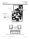
Sample Exhaust - The analyzer exhaust
is vented directly to the atmosphere
through an exhaust line with inner
diameter sufficiently large as not to cause
any back pressure. Internal circuitry
automatically corrects the oxygen readout
to within ±1% of fullscale for atmospheric
pressure variations within ±3% of target
value and within ±2% of fullscale for
barometric pressure variations within ±5%
of target value. The target value may be
set anywhere within range of -2.7 to 3.3
psig ±3 psig (-18.6 to 22.8 kPa ±21 kPa).
d. Operation at Negative Gauge
Pressures
Operation at negative gauge pressures is
not recommended but may be used in
certain special applications. A suction
pump is connected to the analyzer
exhaust port to draw sample into the inlet
and through the analyzer. Such operation
necessitates special precautions to
ensure accurate readout. There is the
basic consideration of supplying the
standard gases to the analyzer at the
same pressure that will be used for the
sample during subsequent operation. In
addition, any leakage will result in
decreased readout accuracy as compared
with operation at atmospheric pressure.
The minimum permissible operating
pressure is -1.9 psig (-13.1 kPa).
Operation below this limit may damage
the detector and will void the warranty.
e. Sample Flow Rate
Operating limits for sample flow rate are
the following: Minimum 50 cc/min.;
maximum 500 cc/min. A flow rate of less
than 50 cc/min. is too slow to sweep out
the detector and associated flow system
efficiently resulting in a slow system
response. Too rapid a flow will cause a
back pressure that will affect the reading.
The optimum flow rate is between 200
and 300 cc/min.
Deviation from the set flow should be held
to within ±1% or ±2 cc/min, whichever is
smaller. If so, zero and span drift will be
within the limits given on the
specifications page, provided that
operating pressure remains constant.
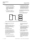
Bypass Flow - Preferably the analyzer
should be installed near the sample
source to minimize transport time.
Otherwise the time lag may be
appreciable. For example, assume that
sample is supplied to the analyzer via a
100 foot (30.5 m) length of 1/4 inch (6.35
mm) O.D. thin walled tubing. With a flow
rate of 100 cc/min., sample transport time
is approximately 6 minutes.
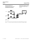
Sample transport time may be reduced by
piping a greater flow than is required to
the analyzer, then routing only the
appropriate portion of the total flow
through the analyzer. The unused portion
of the sample may be returned to the
stream or discarded.