


Instruction Manual
245364-V
May 2002
3-4 Operation Rosemount Analytical Inc. A Division of Emerson Process Management
Model 755A
• Desired oxygen range for recorder
output: 99% to 100%.
•
Front panel TEST switch is set to
position 4, and Recorder Oxygen
Span Jumper is placed in 100%
oxygen (1X gain) position.
•
Required zero suppression is 99%
oxygen, thus Recorder Zero
Suppression Jumper is set in 80%
position, and Recorder Zero
Suppression Adj4ustments R41 and
R104 are set for a reading of 99.00
volts on the digital display.
•
Recorder Oxygen Span Jumper is
returned to 1% oxygen (100X gain)
position, normal span setting for 99%
to 100% oxygen range. R88 may be
used for fine span adjustment.
•
Set front panel TEST switch to
position 1.
3-3 STARTUP PROCEDURE
WARNING
POSSIBLE EXPLOSION HAZARD
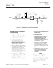
If gases are introduced into this analyzer,
the sample containment system must be
carefully leak-checked upon installation
and before initial start-up, during routine
maintenance and any time the integrity of
the sample containment system is broken,
to ensure the system is in leak-proof
condition. Leak-check instructions are
provided in Section 2-7, page 2-10.
Internal leakage of sample resulting from
failure to observe these precautions could
result in an explosion causing death,
personal injury, or property damage.
Pass suitable on-scale gas (not actual
sample) through the analyzer. Turn power
ON. If digital display gives over-range
indication, the probable cause is hang-up of
the suspension within the detector assembly.
To correct this condition, turn power OFF; tap
detector compartment with fingers; wait 30
seconds; re-apply power.
When on-scale reading is obtained, allow
analyzer to warm up for at least one hour with
gas flowing. This warm-up is necessary
because a reliable calibration is obtainable
only after the analyzer reaches temperature
stability. Moreover, the resultant elevated
temperature will ensure against condensation
within, and possible damage to the detector
assembly.
After analyzer warm-up, the digital display or
recorder should give stable, drift-free readout;
if so, proceed to Section 3.3. Otherwise refer
to Section 6, Service and Maintenance.
3-4 CALIBRATION
Calibration for oxygen readout consists of
establishing a downscale and upscale point.
a. Calibration Using Digital Readout for
Oxygen Readout
The digital display covers the full range of
0.00% to 100.005 oxygen and thus will
normally be used as the readout device
during calibration. If so, almost any
down-scale and upscale standards may
be used. Typically the downscale
standard will be an oxygen-free gas such
as nitrogen, and the upscale standard will
be some readily obtained gas such as dry
air (20.93% oxygen) or 100% oxygen.
Purity requirements will be dictated by the
accuracy requirements of the application.
b. Calibration Using Recorder for Oxygen
Readout
In some applications the recorder readout
may be the important display and may
thus be used during calibration. If so, the
down-scale standard gas is selected to
establish a calibration point at or near the
lower range-limit of the selected range:
1. A zero-based range normally uses an
oxygen-free gas, typically nitrogen.