


Instruction Manual
245364-V
May 2002
2-2 Installation Rosemount Analytical Inc. A Division of Emerson Process Management
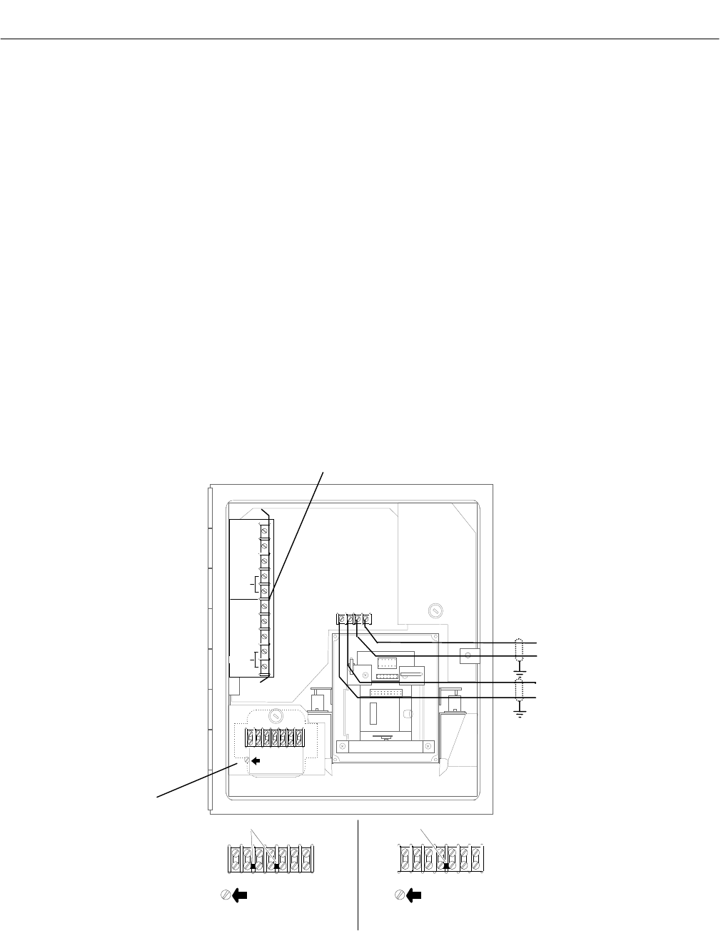
Model 755A
N
E
U
T
H
O
T
TB1
N
E
U
T
H
O
T
TB1
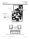
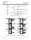
Jumpers
120 VAC CONFIGURATION 240 VAC CONFIGURATION
+ - +
MA
MV
TB2
NO
COM
NC
RESET
NO
COM
NC
RESET
NO. 1
NO. 2
HOT
GND
N
E
U
T
H
O
T
TB1
COM
Jumper
GND GND
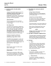
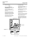
Power Connections
(see below)
Optional Alarm Kit
mV Recorder
mA Recorder
+
-
+
-
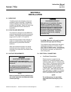
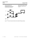
b. Recorder Connections
NOTE
Route recorder cable through a
separate conduit, not with power cable
or alarm output cable.
If a recorder, controller, or other output
device is used, connector it to the
analyzer via a 24-22 AWG two-conductor
shielded cable.
Route the cable through conduit to the
analyzer and into the case through the
appropriate opening shown in Installation
Drawing 642349. Connect the shield only
at the recorder or computer, if used.
Cable connections and output selection
for potentiometric and current actuated
devices are explained in below.
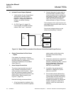
c. Potentiometric Output
Insert Recorder Output Selection Jumper,
Figure 2-2 (page 2-3), in position
appropriate to the desired output; 10 mV,
100 mV, 1V or 5V.
On TB2, Figure 2-1 (page 2-2), connect
leads of shielded recorder cable to "MV+"
AND "COM" terminals.
Connect free end of output cable to
appropriate terminals of recorder or other
potentiometric device.
For device with a span of 0 to 10mV, 0 to
100mV, 0 to 1V, or 0 to 5V, connect cable
directly to input terminals of the device,
making sure polarity is correct.
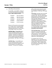
For device with intermediate span, i.e.,
between the specified values, connect
cable to device via a suitable external
voltage divider, as shown in Figure 2-3
(page 2-3).
Figure 2-1. Electrical Connections