


Instruction Manual
245364-V
May 2002
Rosemount Analytical Inc. A Division of Emerson Process Management Theory 4-1
Model 755A
SECTION 4
THEORY
4-1 PRINCIPLES OF OPERATION
Oxygen is strongly paramagnetic while most
other common gases are weakly diamagnetic.
The paramagnetism of oxygen may be
regarded as the capability of an oxygen
molecule to become a temporary magnet
when placed in a magnetic field. This is
analogous to the magnetization of a piece of
soft iron. Diamagnetic gases are analogous to
non-magnetic substances.
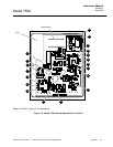
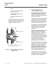
With the Model 755A, the volume magnetic
susceptibility of the flowing gas sample is
sensed in the detector/magnet assembly. As
shown in the functional diagram of Figure 4-2,
(page 4-3), a dumbbell-shaped, nitrogen-filled,
hollow glass test body is suspended on a
platinum/nickel alloy ribbon in a non-uniform
magnetic field.
Because of the “magnetic buoyancy” effect,
the spheres of the test body are subjected to
displacement forces, resulting in a
displacement torque that is proportional to the
volume magnetic susceptibility of the gas
surrounding the test body.
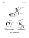
Measurement is accomplished by a
null-balance system, where the displacement
torque is opposed by an equal, but opposite,
restorative torque. The restorative torque is
due to electromagnetic forces on the spheres,
resulting from a feedback current routed
through a titanium wire conductor wound
lengthwise around the dumbbell.
In effect, each sphere is wound with a
one-turn circular loop. The current required to
restore the test body to null position is directly
proportional to the original displacement
torque, and is a linear function of the volume
magnetic susceptibility of the sample gas.
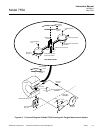
The restoring current is automatically
maintained at the correct level by an
electro-optical feedback system. A beam of
light from the source lamp is reflected off the
square mirror attached to the test body, and
onto the dual photocell.
The output current from the dual photocell is
equal to the difference between the signals
developed by the two halves of the photocell.
This difference, which constitutes the error
signal, is applied to the input of an amplifier
circuit that provides the restoring current.
When the test body is in null position, both
halves of the photocell are equally illuminated,
the error signal is zero, and the amplifier is
unequal. As soon as the test body begins to
rotate, the amounts of light becomes unequal,
resulting in application of an error signal to the
input of the amplifier circuit. The resultant
amplifier output signal is routed through the
current loop, thus creating the
electromagnetic forces required to restore the
test body to null position.
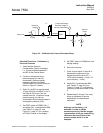
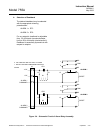
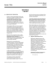
a. Magnetic Displacement Force
Because the magnetic forces on the
spherical ends of the test body are the
basis of the oxygen measurement, it is
worthwhile to consider the force acting on
one of these spheres alone and to
disregard, for the present, the remainder
of the detector. A small sphere
suspended in a strong non-uniform
magnetic field, Figure 4-1 (page 4-2), is
subjected to a force proportional to the
difference between the magnetic
susceptibility of this sphere and that of the
surrounding gas.
Magnitude of the force is expressed by
the following (simplified) equation:
F
k = c (k - ko)