


Instruction Manual
245364-V
May 2002
5-2 Circuit Analysis Rosemount Analytical Inc. A Division of Emerson Process Management
Model 755A
+15V
+15V
INPUT
1
2
+
R69
2M
-
R70
20M
C38
0.18uF
-15V
+15V
R72
4.75K
-
+
R73
20M
-15V
R68
3.3K
R71
21.5K
-1.88 VDC
Source
OUTPUT
159mV
0
°
180
°
360
°
0
°
180
°
100µ
-15V
-1.7V
ON ONOFF
OFF OFFON
COMP 1
COMP 2
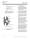
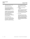
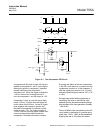
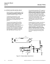
Figure 5-1. Two-Comparator OR Circuit
An approximate 8V peak-to-peak AC signal is
applied to comparators 1 and 2. As the signal
starts going positive, comparator 2 transistor
ceases conducting and comparator 1
transistor is off. When the signal exceeds the
+159 mV on the non-inverting terminal, it
turns on comparator 1 and the output is -15V.
Comparator 1 stays on until the signal drops
below +159 mV, at which time the output will
be the value of the OR bus. As the AC signal
goes negative with respect to ground, the
transistor of comparator 2 conducts and the
output is again -15V. The output remains at
-15VDC until the incoming signal crosses zero
value and the positive signal causes the
comparator 2 transistor to cease to conduct.
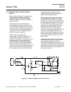
Summing the effects of the two comparators
in the OR circuit results in no output from the
comparators for about 4° of the sinewave, 2°
after the signal goes positive (0 to 2°) and 2°
before the positive signal reaches 180° (178°
to 180°).
During the period that neither comparator is
conducting, the value on the OR bus is the
potential from the temperature-sensing bridge
plus the effect of the ramp generator, probably
-1.88 ±0.03V.
The on-off effect of the comparators to the OR
circuit results in application of a positive-going
pulse (from -15V to -1.89V) to the temperature
bridge at the rate of 120 pulses per second.