


Instruction Manual
245364-V
May 2002
4-6 Theory Rosemount Analytical Inc. A Division of Emerson Process Management
Model 755A
4-3 ELECTRONIC CIRCUITRY
Electronic circuitry and internal
interconnection wiring is shown in the
schematic diagrams and wiring diagram in the
rear of this manual. For detailed circuit
analysis, refer to Section 5.
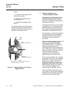
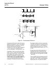
a. Detector/Magnet Assembly
A cross-sectional view of the optical
bench and detector assemblies is shown
in Figure 5-3B. Source lamp DS1,
powered by a supply circuit on the Case
Board (Section 4-3c, page 4-7), directs a
light beam onto the mirror attached to the
test body. The mirror reflects the beam
onto dual photocell BT1, BT2.
The difference between the signals
developed by the two halves of the
photocell constitutes the error signal
supplied to the input of amplifier U1 on
the Control Board. Amplifier U1 drives U2
which, in turn, supplies the restoring
current to the titanium wire loop on the
test body (see Section 4-1, page 4-1).
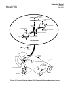
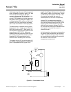
Elements of Detector Temperature
Control Circuit
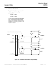
Detector temperature is sensed by
thermistor RT1, an integral part of the
detector assembly (see Figure 4-3B, page
4-4). The thermistor provides the input
signal to the detector temperature control
circuit on the Case Board:
The output from this circuit is applied to
the two heaters within the
detector/magnet assembly; HR1,
mounted on the top of the magnet, and
HR2, mounted permanently on the rear of
the detector assembly.
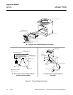
b. Control Board and Associated
Circuitry
The Control Board contains signal
conditioning and control circuitry. The
Control Board is mounted on the inside of
the analyzer door (see Figure 1-2 on page
1-3).
The Control Board contains the following:
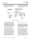
Input Amplifier U1
This amplifier receives the error signal
from the dual photocell of the detector
assembly and drives amplifier U2.
Amplifier U2 and Associated Zero
Adjustment
Amplifier U2 supplies the restoring current
to the titanium wire loop of the test body
within the detector assembly. Front panel
ZERO Control R13 applies an adjustable
zero biasing signal to the input of U2 to
permit establishing a zero calibration point
on the display or recorder. With
downscale zero standard gas flowing
through the analyzer, the ZERO control is
adjusted for the appropriate reading.
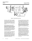
Amplifier U4 and A
S
sociated Span
Adjustment
Amplifier U4 and associated feedback
resistors provide a signal amplification of
X4, resulting in a signal level suitable for
analog divider circuit U6. Front panel
SPAN adjustment R16 modifies the value
of the input resistance and hence the
signal amplification factor. Adjustment
range is approximately ±30%.
The SPAN adjustment permits
establishing an upscale calibration point
on the display or recorder. With upscale
standard gas flowing through the
analyzer, the SPAN control is adjusted for
the appropriate reading.
Pressure Compensation Circuit
The pressure compensation circuit
consists of divider U6 and associated
components. This circuit provides a
pressure-corrected output signal
conditioned to the range of 0 to 10 VDC.
The circuit solves the follow equation:
Vo = k (Vx/Vz)