


Instruction Manual
245364-V
May 2002
Rosemount Analytical Inc. A Division of Emerson Process Management Operation 3-13
Model 755A
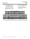
b. Selection of Deadband
The desired deadband may be selected
with the appropriate trimming
potentiometer:
ALARM 1 = R73
ALARM 2 = R78
For any setpoint, deadband is adjustable
from 1% of fullscale (counterclockwise
limit) to 20% of fullscale (clockwise limit).
Deadband is essentially symmetrical with
respect to setpoint.
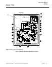
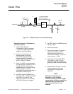
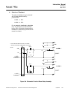
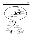
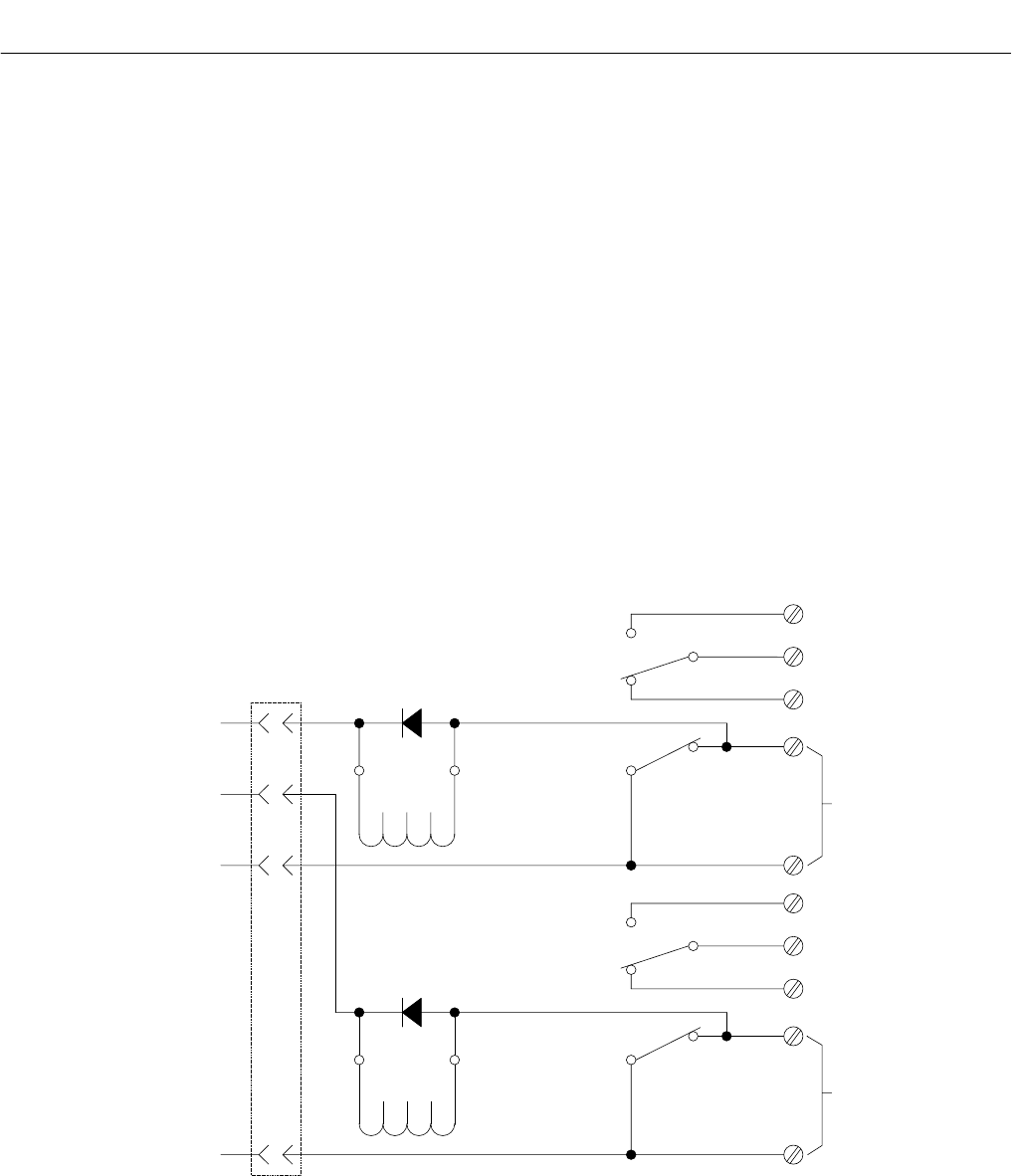
Figure 3-4. Schematic Circuit of Alarm Relay Assembly
+15V
-15V
ALARM 1
COMMAND
ALARM 2
COMMAND
J5
1
2
4
6
14
CR1
13
K1
1
5
9
12 8
NO
COM
NC
RESET
ALARM 1
CR2
13
K2
1
5
9
12 8
NO
COM
NC
RESET
ALARM 2
14
2. CR1 AND CR2 ARE ANY 600V, 1A DIODE.
1. RELAYS SHOWN IN ENERGIZED POSITION.
NOTES: