


Instruction Manual
245364-V
May 2002
6-4 Service and Maintenance Rosemount Analytical Inc. A Division of Emerson Process Management
Model 755A
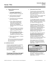
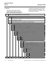
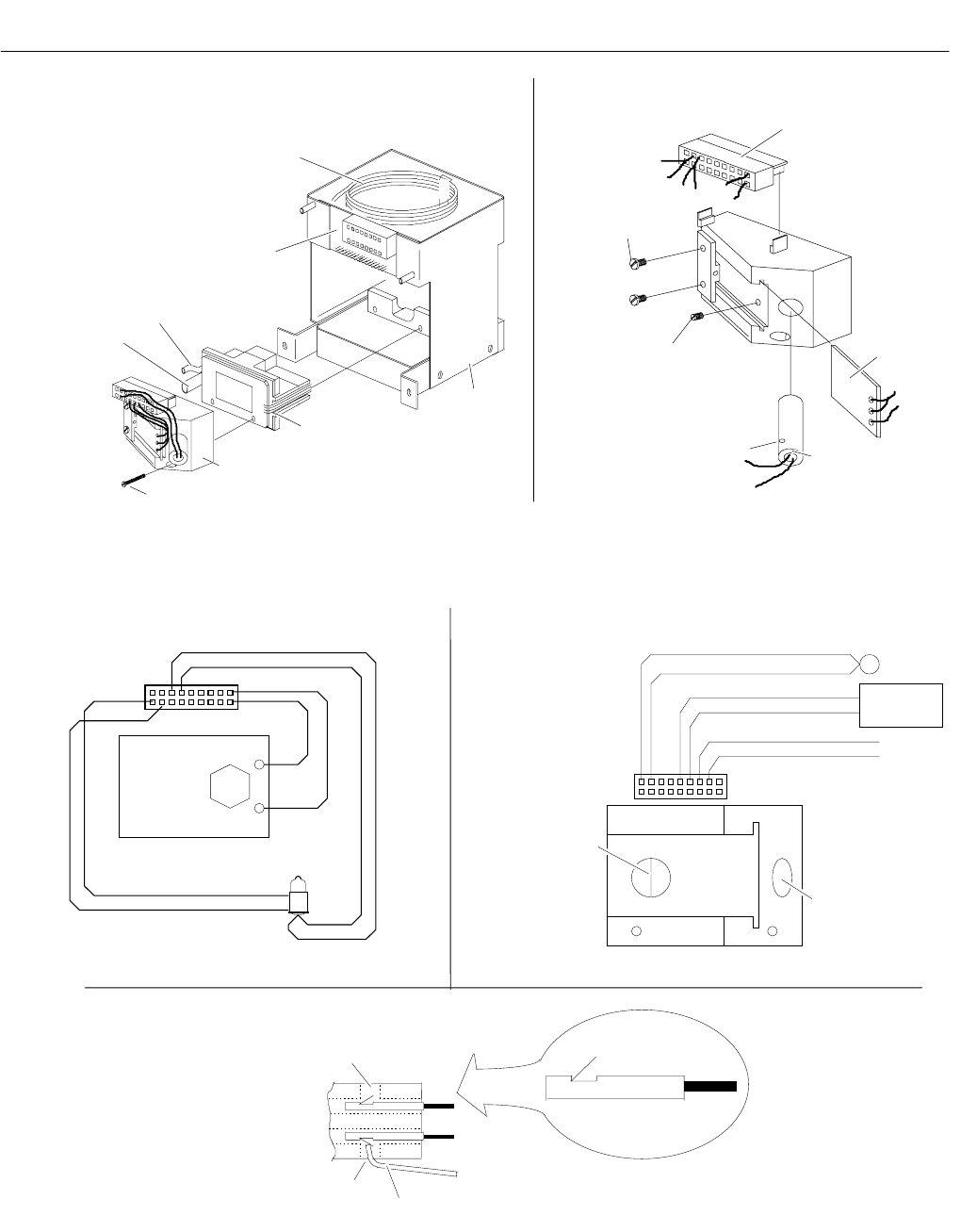
Side View
of Connector
Keeper
Connector Pin Removed
Upper Slot
Lower Slot
Connector Pin/
Leads in Place
Im
p
rovised Pin Removal Tool, Such as a Pa
p
er Cli
p
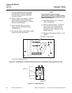
Dual
Photocell
ORN
GRY
RED
BLU
BRN
YEL
Sense
Old St
y
le Lam
p
J12
10 18
1
Hole for Source Lamp
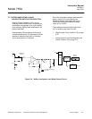
When dual photocell is
installed, the gap between
the two photocells should
be in position indicated by
this line.
O
p
tical Bench
10
J12
1
HR2
Suspension
Heater
PUR
GRN
18
BLK
BLK
WHT
WHT
RT1
Suspension
Terminals
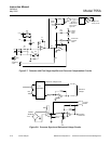
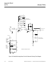
A. Connections to Source Lamp and Photocell B. Connections to Suspension and Heater Circuits
C. Removal and Insertion of Pin/Leads in Connector J12
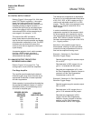
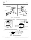
Figure 6-1. Detector/Magnet Assembly
Figure 6-2. Detector/Magnet Assembly Wiring
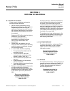
Dual
Photocell
Connector
J12
Lamp Retaining
Set Screw
Photocell
Lock Screws (2)
Lamp Viewing
Hole
Source Lamp
Assembly
Mounting Screws (2)
Optical Bench Assembly
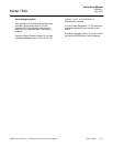
Detector Assembly
Magnet
Assembly
Sample Out-
let Tube
Sample Inlet
Tube
Sample Pre-Heating
Coil
Connector
Board
A. Detector/Magnet Assembly - Exploded View B. Optical Bench - Exploded View