


Instruction Manual
245364-V
May 2002
Rosemount Analytical Inc. A Division of Emerson Process Management Circuit Analysis 5-7
Model 755A
C35
.01uF
-
+
AR7
Q5
DS1
R66
1.0
2
3
+15V
120 V
RMS
6.1 VAC
CR7
CR8
C31
2000uF
R65
4530
R64
14K
R63
7.5K
VR3
9.0V
C34
.01uF
T1
α
2.2V
Q4
α
+8.5V BUS
+
6.1 VAC
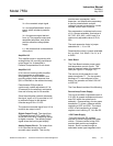
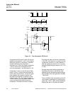
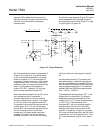
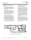
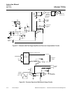
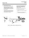
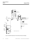
5-5 DETECTOR LIGHT SOURCE CONTROL
CIRCUIT
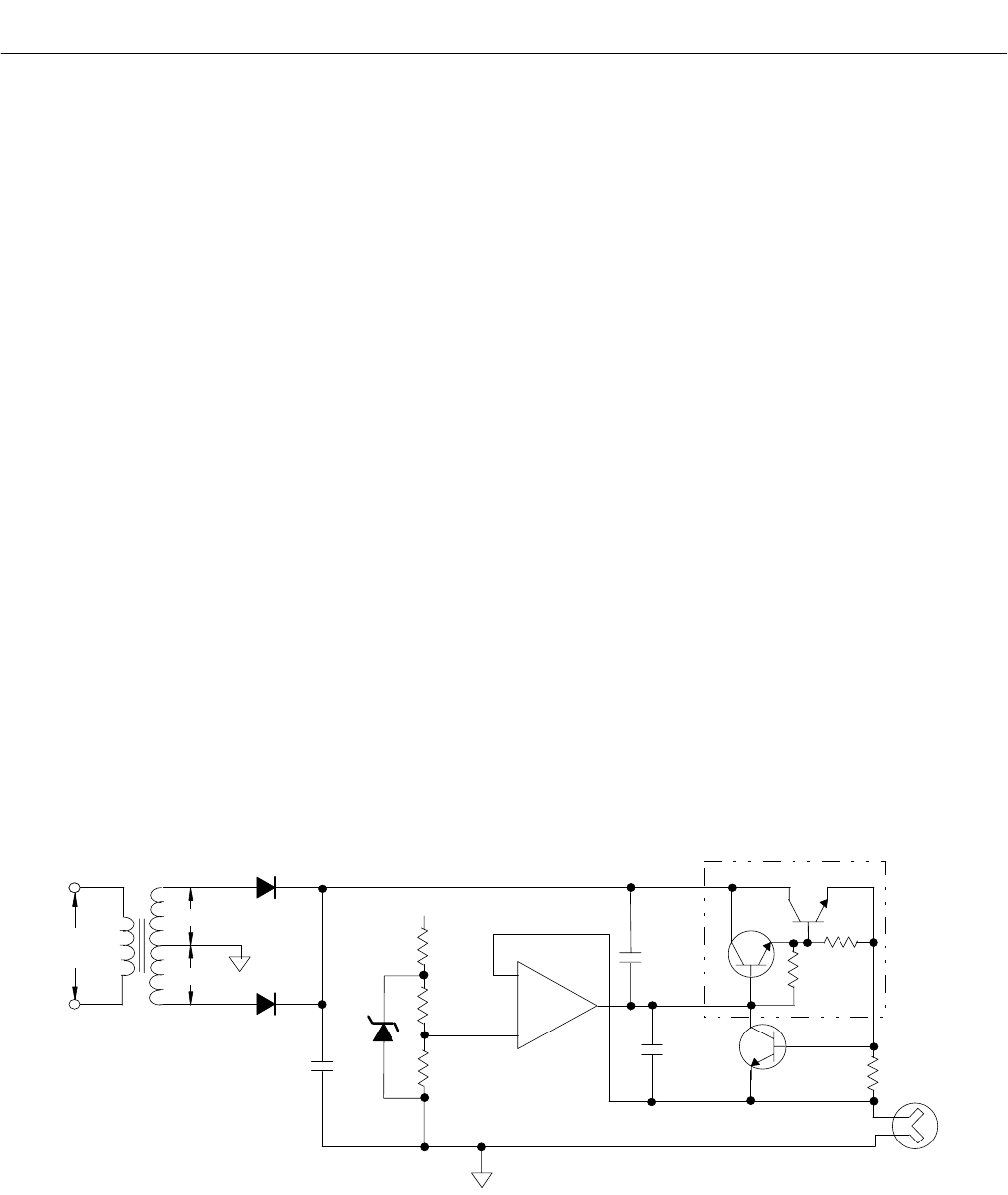
Refer to Figure 5-6 below. The detector light
source control circuit maintains the light
output from the bulb (DS1) as uniform as
possible, regardless of voltage fluctuations or
aging of the bulb.
The power source for the light bulb is a
center-tapped secondary of transformer T1.
This AC voltage is rectified by CR7 and CR8
and filtered (C32), presenting an approximate
+8.5V bus to the current-limiting Darlington
configuration of Q4. Q4 controls the basic
amount of current through DS1.
Amplifier AR7 has a fixed value,
approximately +2.2VDC on terminal 3. The
output of AR7 is positive, causing Q4 to
conduct. As Q4 conducts, electrons flow from
the center-tap of T1 to ground and from
ground through DS1 for an input voltage to
terminal 2 of AR7, through R66 to develop a
bias on the base of Q5, through Q4 to the
+8.5V bus, and back to the secondary. As Q5
conducts, some of the current going through
DS1 is shunted from the main current path,
and goes through Q5, which acts as a
variable feedback resistance, goes to the
positive output potential of AR7.
As DS1 ages, its light emission decreases
and its resistance increases. The current
through DS1 tends to decrease, causing a
decrease in the voltage drop across DS1 and
the input potential to terminal 2 of AR7. Now
the output AR7 will increase, causing Q4 to
conduct more current through R66. As the
potential across R66 increases, Q5 will
conduct more current, causing a further
increase in current flow through DS1. The net
result is that the voltage across DS1 will
remain uniform and the operation of Q4 and
Q5 will adjust the gain of AR7 to maintain the
light emission from DS1 uniform for a long
period of time.
Voltage fluctuations in the 115VAC supply
could cause some variation in the amount of
current flowing through the bulb DS1.
However, the voltage drop across DS1 would
cause AR7 to adjust Q4 and the voltage drop
across R66 to adjust Q5. The net result would
still be uniform current flow through DS1 and
uniform light emission.
Figure 5-6. Detector Light Source Control Circuit