


Instruction Manual
245364-V
May 2002
Rosemount Analytical Inc. A Division of Emerson Process Management Installation 2-3
Model 755A
R2 R1
R3
R4
R5
R6
R8
R9
CR2
U6
I G O
U3
U2
1
2
3
4
I
G
O
C5
C4
C2
U4
U5
I G O
C3 CR1 C1
U1
J1
JP3
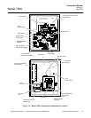
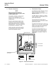
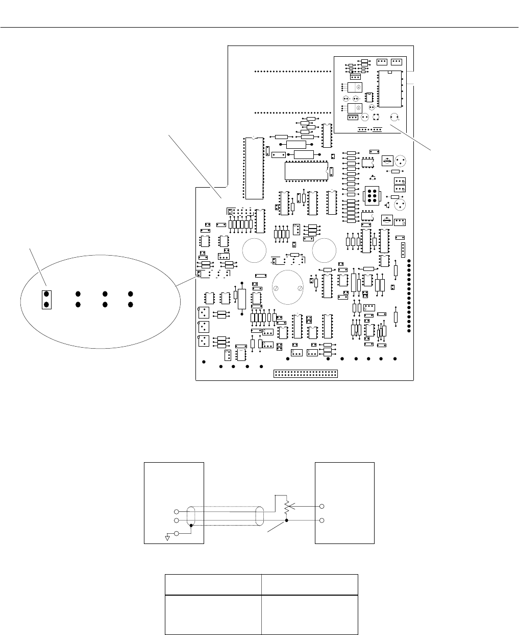
Control Board
Current Output
Board
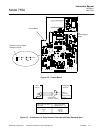
5V 1V 0.1V 0.01V
Recorder Output Voltage
Selection Jumper
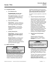
Figure 2-2. Control Board
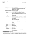
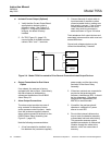
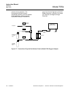
Figure 2-3. Connections for Potentiometric Recorder with Non-Standard Span
755A
Analyzer
Potentiometric
Recorder
Input
Terminals
(Make sure polarity
is correct)
Voltage Divider
(Customer Supplied)
Position of Recorder Output
Selector Plug
Minimum Permissible
Resistance for R1 + R2
10 mV 1K Ohm
100 mV 10K Ohm
1 V 100K Ohm
5 V 2K Ohm