


Instruction Manual
245364-V
May 2002
5-12 Circuit Analysis Rosemount Analytical Inc. A Division of Emerson Process Management
Model 755A
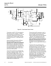
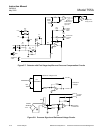
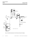
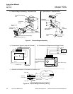
5-8 DIGITAL OUTPUT CIRCUIT
Refer to Figure 5-10 on page 5-14. With front
panel TEST Switch in position 1, the output
signal from buffer amplifier U10 is routed
through an attenuator and filter network to an
integrating analog-to-digital converter. It
converts the signal into an equivalent digital
value in the range of 0.00% to 99.99%. Any
value above 99.99% will be preceded by an
over-range bit, for example, 1.1123.
The output of the ADC consists of
binary-coded decimal characters that are
input to the liquid crystal controller and display
chip characters sequentially in time. The BCD
characters are converted into seven-line
codes to drive the bar segments of the liquid
crystal display.
A separate regulator circuit, which operates
from the +15VDC supply, provides a
regulated 5VDC for the digital functions
associated with the display.
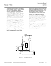
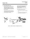
5-9 ANALOG OUTPUT CIRCUITS FOR
RECORDER AND ALARMS
Refer to Figure 5-10 on page 5-14. The
analog output circuits utilize two amplifiers:
First Stage Amplifier
This amplifier permits selecting the desired
fullscale oxygen range for the recorder by an
appropriate combination of scale expansion
and zero suppression.
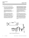
Scale expansion is accomplished by selecting
the appropriate feedback resistor in a switch-
selectable network, thus establishing one of
six values for amplifier gain:
DESIRED OXYGEN
SPAN FOR
RECORDER
REQUIRED
AMPLIFIER GAIN
100% 1X
20% 5X
10% 10X
5% 20X
2% 50X
1% 100X
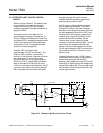
The desired zero suppression is obtained as
the sum of (a) a jumper-selectable fixed value
of 0%, 20%, 40%, or 80% oxygen and (b) a
continuously adjustable value of 0% to 25%
oxygen. Thus the total zero suppression may
be set for any desired valued from 0% to
105% oxygen.
In order to establish the precise zero
suppression required for the recorder output,
the actual applied zero suppression may be
read on the digital display by placing the front
panel TEST Switch in position 4 and the
recorder scale-expansion jumper in the 100%
(i.e., 1X gain) position.
Note that, in this mode the signal input is
disconnected, allowing only the input offset
current for the zero-suppression function to
flow into the amplifier summing node.
Example 1, Selection of a Zero Based
Recorder Oxygen Range:
Desired oxygen range for recorder output:
0% to 100%
Required span is 100% oxygen; thus a
gain of 1 is selected with the jumper.
Required zero suppression is 0%; thus,
the Zero Suppression Selection Jumper is
removed, and the Zero Suppression
Potentiometer is set for 0%.
Example 2, Selection of a Zero Suppression
Recorder Oxygen Range:
Desired oxygen range for recorder output:
90% to 100%.
Required span is 10% oxygen; thus, a
gain of 10 is selected with the jumper.
Required zero suppression is 90%
oxygen; thus the Zero Suppression
Selection Jumper is placed in the 80%
position, and the Zero Suppression
Potentiometer is set for 10% oxygen.