


Instruction Manual
245364-V
May 2002
5-4 Circuit Analysis Rosemount Analytical Inc. A Division of Emerson Process Management
Model 755A
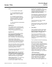
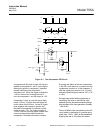
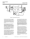
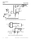
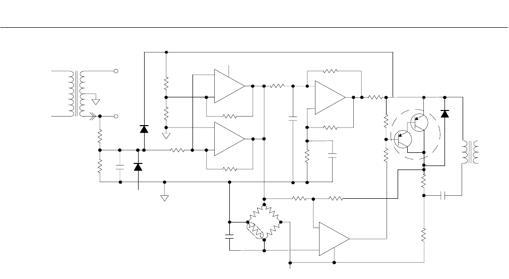
Figure 5-3. Case Heater Control Circuit
Theoretically, at 135°F (57°C) the potential at
the junction of RTR1 and R84 is -1.85VDC.
This is equivalent to a resistance of 21.2 K. By
substituting a decade box for the thermistor
and placing 20.2 K into the bridge, the heater
should be off. With 22.7 K, the heater should
be full on.
Since the potential at the junction of R82 and
R83 can vary between 1.85V and 1.92V
according to the 6 Hz ramp, and the potential at
the junction of RT1 and R84 may vary around or
within these limits, depending on temperature,
the error signal to comparator 4 may vary from
0 mV to some absolute value. The polarity of the
error signal will depend on the deviation from
the desired temperature and the ramp value at
the function of R82 and R83.
The input from the OR circuit comparator (See
Figure 5-1 on page 5-2) is either -15VDC or the
ramp effect on the bridge. When -15V, the
junction of R82 and R83 is also this value. The
error signal into comparator 4 is negatively large
to the inverting terminal. Comparator 4 output
transistor does not conduct. The base of Q6 is
positive; therefore, Q6 does not conduct and a
charge builds up on capacitor C38.
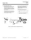
The input from the OR comparators 1 and 2, a
form of multivibrator circuit, pulses 120 times a
second. For about 100 microseconds the
junction of R82 and R83 is some value between
-1.85V and -1.92V, depending on the ramp
generator. For this brief period of time (one
pulse), comparator 4 compares the potential of
junction R82, R83 with junction RT1, R84 of the
bridge circuit. If the temperature at RT1 is low,
the potential at the non-inverting terminal of
comparator 4 is more negative and the output is
-15V.
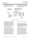
The base of Q6 is zero, because of the
voltage drops across R79 and R80; therefore,
Q6 conducts. Energy, stored in C38, flows
through Q6 as current and capacitor C38
discharges to zero potential. No current flows
through the primary winding of transformer
T2. At the end of the 100 microsecond pulse,
the NPN transistor in the output of comparator
4 ceases to conduct, so the signal on the
base of Q6 is +15V. Q6 ceases to conduct.
C38 starts to charge, driving electrons
(current) through the primary of T2. This
induces a pulse into the secondary of T2 and
to the gate of Triac Q7 (Figure 5-5 on page 5-
6) turning it on.
120 V
RMS
T1
19 VAC
TO POWER
SUPPLY
19 VAC
12
R67
10K
R72
4.75K
C36
.18uF
CR10
CR9
-15V
R71
21.5K
R69
2 M
R68
3.3K
R70
20M
R73
20M
R74
590K
+15V
-
+
1
-
+
2
-
+
3
-
+
4
R75
210K
R85
11.0K
R86
20M
R76
37.4K
C40
2200uF
C37
1.0uF
C39
.01uF
R83
63.4K
R84
169K
R82
9.07K
RT1
-15V
R78
249K
Q6
R80
10K
R79
10K
R81
56.2
C38
.18uF
R87
10K
R77
10K
CR11
T2