


Instruction Manual
245364-V
May 2002
Rosemount Analytical Inc. A Division of Emerson Process Management Installation 2-1
Model 755A
SECTION 2
INSTALLATION
2-1 UNPACKING
Carefully examine the shipping carton and
contents for signs of damage. Immediately
notify the shipping carrier if the carton or its
contents are damaged. Retain the carton and
packing materials until the instrument is
operational.
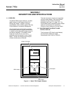
2-2 LOCATION AND MOUNTING
The analyzer is designed to meet NEMA 3R
enclosure requirements and may be mounted
outdoors. Permissible ambient temperature
range is 20°F to 120°F (-7°C to 49°C).
Avoid mounting outside in direct sunlight, or
inside in a closed building, where ambient
temperature may exceed the allowable
maximum.
Shock and mechanical motion can reduce
instrument accuracy; therefore, mount the
instrument in an area that is as vibration free
as possible.
2-3 VOLTAGE REQUIREMENTS
WARNING
ELECTRICAL SHOCK HAZARD
live parts which can cause death or
serious injury. Refer servicing to qualified
personnel.
For safety and proper performance this
instrument must be connected to a
properly grounded three-wire source of
power.
NOTE
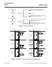
Refer to Installation Drawing 642349 at the
rear of this manual for recommended cable
conduit openings.
CAUTION
ENCLOSURE INTEGRITY
With reference to Installation Drawing
642349, any unused cable conduit
openings must be securely sealed by
permanent closures in order to provide
enclosure integrity in compliance with
personnel safety and environmental
protection requirements. The plastic
closures provided are for shipping
protection only.
NOTE
For NEMA 3R service, all conduit must be
connected through approved fittings.
This instrument was shipped from the factory
configured to operate on 115 VAC or 240
VAC, 50/60 Hz electric power. Verify that the
power source conforms to the requirements of
the individual instrument, as noted on the
name-rating plate.
2-4 ELECTRICAL CONNECTIONS
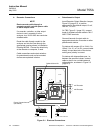
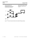
a. Line Power Connections
Electrical power is supplied to the
analyzer via a customer-supplied, three-
conductor cable, type SJT, minimum wire
size 18 AWG. Route power cable through
conduit and into appropriate opening in
the instrument case (see Installation
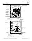
Drawing 642349). Connect power leads
to HOT, NEUT, AND GND terminals on
TB1, see Figure 2-1 (page 2-2). Connect
analyzer to power source via an external
fuse, in accordance with local codes.
NOTE
Do not draw power for associated
equipment from the analyzer power
cable.