


Instruction Manual
245364-V
May 2002
Rosemount Analytical Inc. A Division of Emerson Process Management Circuit Analysis 5-3
Model 755A
-15V
R74
590K
-
+
3
R75
210K
R76
37.4K
C40
2200uF
C37
1.0uF
Q6
R80
10K
R79
10K
R81
56.2
C38
.18uF
R87
10K
R78
249K
R77
10K
TO
COMPARATOR
R83
63.4K
R84
169K
R82
9.09K
RT1
-15V
-15V to 1.88V
±
0.3V
+15V
+15V
-15V
INPUT FROM
MULTIVIBRATOR
-15V
OFF OFF
OFF
-2.3V
+2.3V
6 Hz
T2
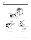
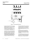
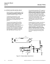
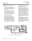
Capacitor C36 is added to the input circuit to
delay the incoming AC signal so that the pulses
will occur at or just after the line frequency
crossover point.
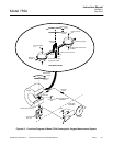
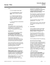
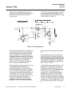
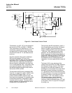
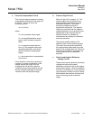
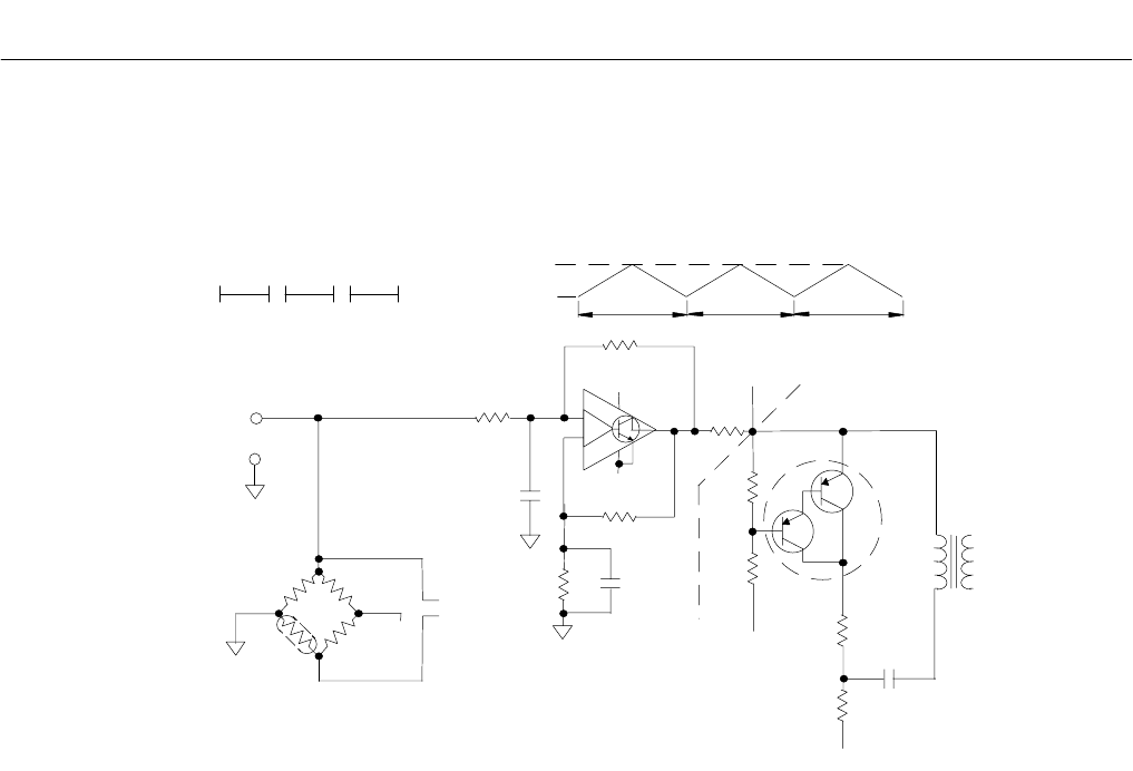
Circuits for a ramp generator (Figure 5-2 below)
and a temperature-sensing bridge are part of
the case heater control circuit (Figure 5-3, page
5-4 and Figure 5-4, page 5-5).
Figure 5-2. Ramp Generator
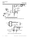
On initial application of power to comparator 3
(Figure 5-3 on page 5-4), no potential exists
on the inverting terminal because no charge
exists on capacitor, C37. If the transistor of
comparator 3 does not conduct, +15V is at the
output terminal. With +15V at the output, the
potential on the non-inverting terminals will be
about ±2.3V because of the resistance
divider, R75, R76. Capacitor C37 will now
start to charge positively through R78.
When the positive potential across C37 and at
the inverting terminal of comparator 3
exceeds the potential on the non-inverting
terminals, the transistor conducts. The output
is -15V. A full 30V drop appears across R77.
The potential on the non-inverting terminal will
now be about -2.3V. C37 will not discharge
through R78 until its potential exceeds that on
the non-inverting terminal. At that time,
comparator 3 will switch polarity and start
charging C37 again. The result is that the
potential across C37 will vary almost linearly
with time and form a ramp signal of about 6
Hz.
As the potential across C37 increases and
decreases linearly, it affects the potential at
the top of the bridge circuit between R82 and
R83 through R74. Because of the ramp action
charging and discharging C37, the potential
between R82 and R83 varies approximately
from -1.85V to -1.92VDC.
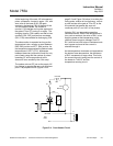
The temperature sensing device, RT1, in the
bridge circuit is a thermistor. The bridge is
designed to control the temperature in the
case at 135°F (57°C). When the temperature
is 135°F (57°C), the resistance of the
thermistor RT1 will be at its lowest and the
potential at the junction of RT1 and R84
should be the same as the junction of R82
and R83. Comparator 4 (Figure 5-4 on page
5-5) does not allow pulses from the OR circuit
(comparators 1 and 2) to operate Q6 or Triac
Q7 in the case heater (Figure 5-5 on page 5-
6).