


Instruction Manual
245364-V
May 2002
Rosemount Analytical Inc. A Division of Emerson Process Management Installation 2-5
Model 755A
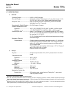
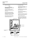
g. Alarm Relay Characteristics
The ALARM 1 and ALARM 2. Outputs of
the Alarm Relay Assembly are provided
by two identical single-pole double-throw
relays. Relay contacts are rated:
5 amperes 240 VAC resistive
1 ampere 240 VAC inductive
5 amperes 120 VAC resistive
3 amperes 120 VAC inductive
5 amperes 30 VDC resistive
3 amperes 30 VDC inductive
Removal of AC power from the analyzer,
as in a power failure, de-energizes both
relays, placing them in alarm condition.
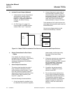
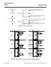
Switching characteristics of the ALARM 1
and ALARM 2 relays are as follows:
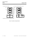
ALARM 1 Relay - The ALARM 1 relay
coil is de-energized when the meter
needle moves downscale through the
value that corresponds to setpoint minus
deadband. This relay coil is energized
when the needle moves upscale through
the value that corresponds to setpoint
plus deadband. See Figure 2-5A, page 2-
6.
ALARM 2 Relay - The ALARM 2 relay
coil is de-energized when the meter
needle moves upscale through the value
that corresponds to the setpoint plus
deadband. This relay coil is energized
when needle moves downscale through
the value that corresponds to setpoint
minus deadband. See Figure 2-5B, page
2-6.
Alarm Reset - Normally both the ALARM
1 and ALARM 2 functions incorporate
automatic reset. When the meter reading
goes beyond the pre-selected limits, the
corresponding relay is de-energized.
When the meter reading returns within the
acceptable range, the relay is
automatically substituting an external
pushbutton or other momentary-contact
switch for the jumper that normally
connects the RESET terminals on the
Alarm Relay Assembly. If the
corresponding relay is now de-energized,
i.e., in alarm condition, the relay remains
de-energized until the operator
momentarily closes the switch.
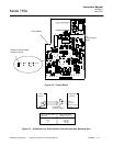
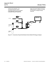
Fail-Safe Applications - By appropriate
connection to the double-throw relay
contacts, it is possible to obtain either a
contact closure or a contact opening for
an energized relay. Also, either a contact
closure or a contact opening may be
obtained for a de-energized relay.
It is important that, for fail-safe
applications, the user understand wheat
circuit conditions are desired in the event
of power failure and the resultant relay
de-energization. Relay contacts should
then be connected accordingly. Refer to
Figure 2-6, page 2-6.