


Instruction Manual
245364-V
May 2002
2-6 Installation Rosemount Analytical Inc. A Division of Emerson Process Management
Model 755A
NO
COM
NC
NO
COM
NC
RESET
RESET
No. 1
No. 2
Alarm Bell
or Lamp
N
H
115 VAC
NO
COM
NC
NO
COM
NC
RESET
RESET
No. 1
No. 2
Alarm Bell
or Lamp
N
H
115 VAC
NO
COM
NC
NO
COM
NC
RESET
RESET
No. 1
No. 2
NO
COM
NC
NO
COM
NC
RESET
RESET
No. 1
No. 2
Alarm Bell
or Lamp
N
H
115 VAC
NO
COM
NC
NO
COM
NC
RESET
RESET
No. 1
No. 2
Alarm Bell
or Lamp
N
H
115 VAC
NO
COM
NC
NO
COM
NC
RESET
RESET
No. 1
No. 2
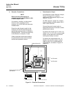
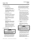
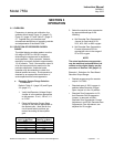
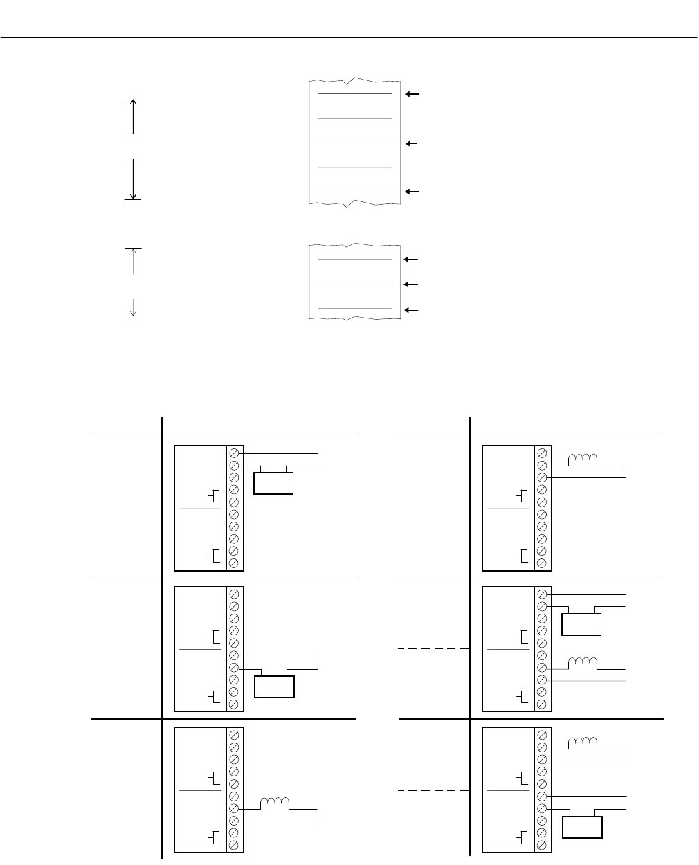
REQUIREMENT TYPICAL CONNECTIONSREQUIREMENT TYPICAL CONNECTIONS
Low Alarm,
Fail-Safe
Low Control
Limit,
Fail-Safe
Solenoid
Valve
N
H
115 VAC
High Alarm,
Fail-Safe
Low Control
Limit,
Fail-Safe
Solenoid
Valve
N
H
115 VAC
Solenoid
Valve
N
H
115 VAC
Lower
Low Alarm
Indicator,
Fail-Safe
Low Control,
Fail-Safe
Higher
High Alarm
Indicator,
Fail-Safe
High Control,
Fail-Safe
Solenoid
Valve
N
H
115 VAC
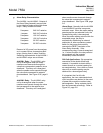
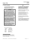
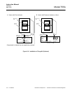
When input signal moves upscale through this point, the coil of
ALARM 1 relay (K1) is energized, providing continuity between the
common and normally-closed contacts of the relay.
ALARM 1 Setpoint
When input signal moves downscale through this point, the coil of
ALARM 1 relay (K1) is de-energized, providing continuity between the
common and normally-open contacts of the relay.
ALARM 2 Setpoint
When input signal moves upscale through this point, the coil of ALARM
2 relay (K2) is de-energized, providing continuity between the common
and normally-open contacts of the relay.
When input signal moves upscale through this point, the coil of ALARM
2 relay (K2) is energized, providing continuity between the common
and normally-closed contacts of the relay.
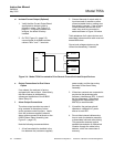
A. Typical ALARM 1 Setting
DEADBAND SET FOR
20% OF FULLSCALE
DEADBAND SET FOR
10% OF FULLSCALE
B. Typical ALARM 2 Setting
INPUT SIGNAL
Percent of Fullscale
INPUT SIGNAL
Percent of Fullscale
40
30
20
55
50
45
Figure 2-5. Typical Alarm Settings
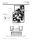
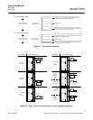
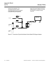
Figure 2-6. Relay Terminal Connections for Typical Fail-Safe Application