


Instruction Manual
245364-V
May 2002
2-4 Installation Rosemount Analytical Inc. A Division of Emerson Process Management
Model 755A
755A
Analyzer
Recorder
Controller
Remote
Indicator
+
-
+
-
+
-
+
-
mA
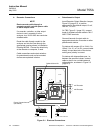
d. Isolated Current Output (Optional)
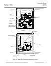
1. Verify that the Current Output Board
appropriate to desired output is
properly in place. See Figure 2-2,
page 2-3. If originally ordered with
analyzer, the board is factory
installed.
2. On TB2, Figure 2-1 (page 2-2),
connect leads of shielded recorder
cable to "MA+" and "-" terminals.
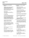
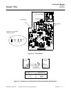
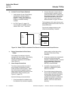
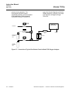
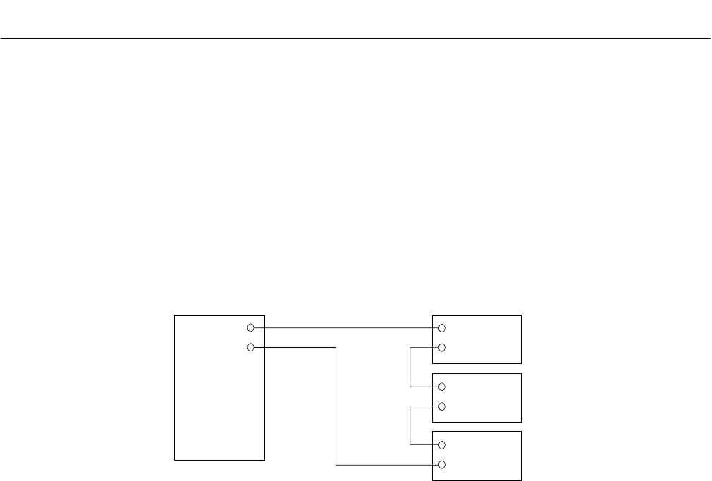
3. Connect free end of output cable to
input terminals of recorder or other
current actuated device, making sure
that polarity is correct. If two or more
current-actuated devices are to be
used, they must be connected in
series as shown in Figure 2-4 below
Total resistance of all output devices and
associated interconnection cable must not
exceed 850 ohms.
Current and voltage outputs may be
utilized simultaneously, if desired.
Figure 2-4. Model 755A Connected to Drive Several Current-Activated Output Devices
e. Output Connections for Dual Alarm
Option
If so ordered, the analyzer is factory-
equipped with alarm output. Alternatively,
the alarm feature is obtainable by
subsequent installation of the 618083
Alarm Relay Kit.
f. Alarm Output Connections
The alarm output provides two sets of
relay contacts for actuation of alarm
and/or process control functions. Leads
from the (customer-supplied) external
alarm system connect to terminals on the
638254 Alarm Relay Assembly (see
Figure 2-1, page 2-2).
Note the following recommendations:
1. A line fuse should be installed in the
line between the (customer-supplied)
power supply and the alarm relay
terminals on the Alarm Relay
Assembly.
2. If the alarm contacts are connected to
any device that produces radio
frequency interference (RFI), it should
be arc-suppressed. Rosemount
Analytical Arc Suppression (PN
858728) is recommended.
3. If possible, the analyzer should
operate on a different AC power
source to avoid RFI.
4. Do not allow internal cable service
loop to touch the detector assembly
or associated inlet and outlet tubing.
This precaution ensures against
possible transmission of mechanical
vibration through the cable to the
detector, which can cause loss of
accuracy.