


Basic Operation Teledyne API T802 Paramagnetic O
2
Analyzer Operation Manual
66
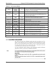
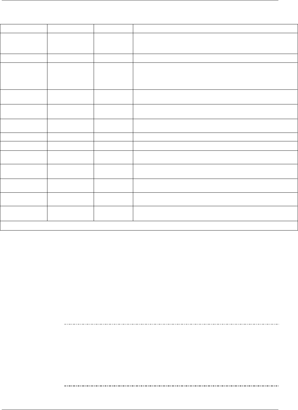
Table 4-2: Test Functions Defined
PARAMETER DISPLAY TITLE UNITS MEANING
Range
RANGE
RANGE1
RANGE2
%
The full scale limit at which the reporting range of the analyzer is
currently set. THIS IS NOT the Physical Range of the instrument.
See Section 5.4.1 for more information.
CO
2
Range
1
CO2 RANGE
%
The range setting for the optional CO
2
Sensor
Stability
STABIL
%
Standard deviation of O
2
concentration readings. Data points are
recorded every ten seconds using the last 25 data points. This
function can be reset to show O
2
or CO
2
stability in instruments with
those sensor options installed.
Sample Pressure
PRES
In-Hg-A
The absolute pressure of the Sample gas as measured by a
pressure sensor located inside the sample chamber.
Sample Flow
SAMPLE FL
cm
3
/min
Sample mass flow rate as measured by the flow rate sensor in the
sample gas stream.
O
2
Sensor
Slope
O2 SLOPE
- O
2
slope, computed during zero/span calibration.
O
2
Sensor Offset
O2 OFFSET
- O
2
offset, computed during zero/span calibration.
Box Temperature
BOX TEMP
C
The temperature inside the analyzer chassis.
O
2
Cell
Temperature
O2 CELL TEMP
C
The current temperature of the O
2
sensor measurement cell.
CO
2
Cell
Temperature
1
CO2 CELL
TEMP
C
The current temperature of the CO
2
sensor measurement cell.
CO
2
Sensor
Slope
1
CO2 SLOPE
- CO
2
slope, computed during zero/span calibration.
CO
2
Sensor
Offset
1
CO2 OFFSET
- CO
2
offset, computed during zero/span calibration.
Current Time
TIME
-
The current time. This is used to create a time stamp on DAS
readings, and by the AUTOCAL feature to trigger calibration events.
1
Only appears when the optional CO
2
sensor is installed.
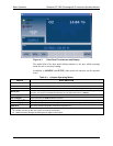
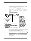
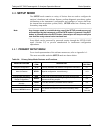
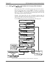
4.3. CALIBRATION MODE
The T802 will switch into calibration mode when the user touches the CAL
button. In this mode the user can, in conjunction with introducing zero or span
gases of known concentrations into the analyzer, cause it to adjust and recalculate
the slope (gain) and offset of the its measurement range. This mode is also used
to check the current calibration status of the instrument.
For more information about setting up and performing standard calibration
operations or checks, see Section 9, Calibration Procedures.
Note
It is recommended that span calibration be performed at 80% of full scale of
the analyzer’s currently selected reporting range.
EXAMPLES:
If the reporting range is set for 0 to 50%, an appropriate span point would
be 40%.
If the of the reporting range is set for 0 to 100%, an appropriate span point
would be 80%.
07275B DCN6418