


Troubleshooting and Service Teledyne API T802 Paramagnetic O
2
Analyzer Operation Manual
212
11.6.9. MOTHERBOARD
11.6.9.1. A/D FUNCTIONS
The simplest method to check the operation of the A-to-D converter on the
motherboard is to use the Signal I/O function under the DIAG menu to check the
two A/D reference voltages and input signals that can be easily measured with a
voltmeter.
1. Use the Signal I/O function (See Section 11.1.3 and Appendix A) to view the
value of REF_4096_MV and REF_GND.
If both are within 3 mV of nominal (4096 and 0), and are stable, ±0.2 mV
then the basic A/D is functioning properly. If not then the motherboard is
bad.
2. Choose a parameter in the Signal I/O function such as
SAMPLE_PRESSURE or SAMPLE_FLOW.
Compare these voltages at their origin (see interconnect drawing PN
06407 and interconnect list PN 06294 in Appendix D) with the voltage
displayed through the signal I/O function.
If the wiring is intact but there is a large difference between the measured
and displayed voltage (±10 mV) then the motherboard is bad.
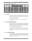
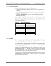
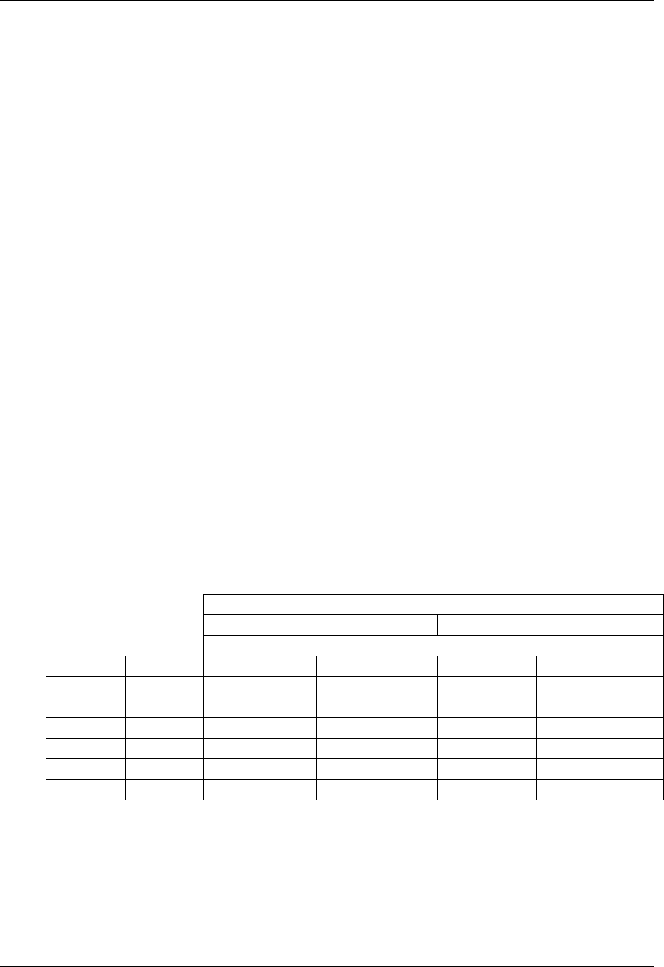
11.6.9.2. ANALOG OUTPUTS: CURRENT LOOP
To verify that the analog outputs with the optional current mode output are
working properly, connect a 250 ohm resistor across the outputs and use a
voltmeter to measure the output as described in Section 5.9.3.6.
For each step
the output s
hould
be within 1% of the nom
inal value listed in the
table below.
Table 11-7: Analog Output Test Function - Nominal Values Current Outputs
OUTPUT RANGE
2 -20 4 -20
NOMINAL OUTPUT VALUES
STEP % CURRENT V(250 OHMS) CURRENT V(250 OHMS)
1 0 2 mA 0.5V 4 1
2 20 5.6 1.4 7.2 1.8
3 40 9.2 2.3 10.4 2.6
4 60 12.8 3.2 13.6 3.4
5 80 16.4 4.1 16.8 4.2
6 100 20 5 20 5
07275B DCN6418