Troubleshooting and Service Teledyne API T802 Paramagnetic O
2
Analyzer Operation Manual
208
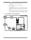
4. Disconnect the exhaust line from the optical bench near the rear of the
instrument and plug this line into the SAMPLE inlet creating a pneumatic
loop. The concentration (either zero or span) now must be constant. If
readings become quiet, the problem is in the external pneumatics supplies for
sample gas, span gas or zero air.
11.4.3. INABILITY TO SPAN – NO SPAN BUTTON
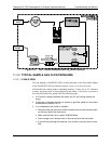
1. Confirm that the oxygen span gas source is accurate; this can be done by
opening the analyzer’s SAMPLE inlet to ambient air. If the concentration is
not displayed as ~20.9%, there is a problem with the span gas.
2. Check for leaks in the pneumatic systems as described in Section 10.3.3.
3. Make sure th
at the expected span gas concentration entered into the
instrument during calibration, is the correct span gas concentration and not
too different from expected span value. This can be viewed via the CONC
submenu of the Sample displays.
4. Check to make sure that there is no ambient air or zero air leaking into span
gas line.
11.4.4. INABILITY TO ZERO – NO ZERO BUTTON
1. Confirm that there is a good source of zero air. Dilute a tank of span gas with
the same amount of zero air from two different sources. If the O
2
Concentration of the two measurements is different, there is a problem with
one of the sources of zero air.
2. Check for leaks in the pneumatic systems as described in 10.3.3.
3. Check to make sure that there is n
o ambient air leaking into zero air line.
11.5. OTHER PERFORMANCE PROBLEMS
Dynamic problems (i.e. problems which only manifest themselves when the
analyzer is monitoring sample gas) can be the most difficult and time consuming
to isolate and resolve. The following provides an itemized list of the most
common dynamic problems with recommended troubleshooting checks and
corrective actions.
11.5.1. TEMPERATURE PROBLEMS
Individual control loops are used to maintain the set point of the absorption
bench, filter wheel and IR photo-detector temperatures. If any of these
temperatures are out of range or are poorly controlled, the T802 will perform
poorly.
11.5.1.1. BOX TEMPERATURE
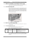
The box temperature sensor is mounted to the motherboard and cannot be
disconnected to check its resistance. Rather check the BOX TEMP signal using
the SIGNAL I/O function under the DIAG Menu (See Section 5.9). This
param
eter will vary
with ambient temperature, but at ~30
o
C (6-7° above room
temperature) the signal should be ~1450 mV.
07275B DCN6418


