


Teledyne API T802 Paramagnetic O
2
Analyzer Operation Manual Troubleshooting and Service
203
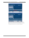
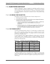
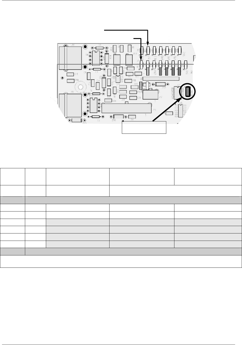
11.2.2.2. RELAY PCA STATUS LED S
D6
(
Y
ellow
)
O
2
Sensor Heater
D5 (Yellow) – CO
2
Sensor Heater
(only with CO
2
option)
D1 (RED)
Watchdog Indicator
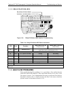
Figure 11-4: Relay PCA Status LEDS Used for Troubleshooting
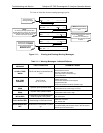
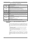
Table 11-4: Relay PCA Status LED Failure Indications
LED Color Function
Status When LED Lit
(Energized State)
Status When LED Unlit
(Default State)
D1
Red Watchdog Circuit
Cycles ON/OFF every 3 Seconds
under direct control of the analyzer’s CPU.
D2-D4 SPARE
D5
1
Yellow CO
2
Sensor Cell heater Heating Not Heating
D6
Yellow O
2
Sensor heater Heating Not Heating
D7
2
Green
D8
2
Green
D9
2
Green
D10
2
Green
D11 - 16 SPARE
1
Only active when the optional CO
2
sensor is installed
2
Not Used
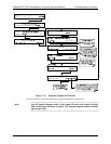
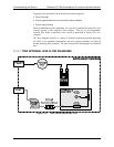
11.3. GAS FLOW PROBLEMS
When troubleshooting flow problems, it is a good idea to first confirm that the
actual flow and not the analyzer’s flow sensor and software are in error, or the
flow meter is in error. Use an independent flow meter to perform a flow check as
described in Section 10.3.4. If this test shows the flow to be correct, check the
pressure sens
ors as described in Section 11.6.8.
07275B DCN6418