


Teledyne API T802 Paramagnetic O
2
Analyzer Operation Manual Principles of Operation
227
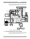
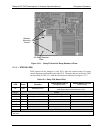
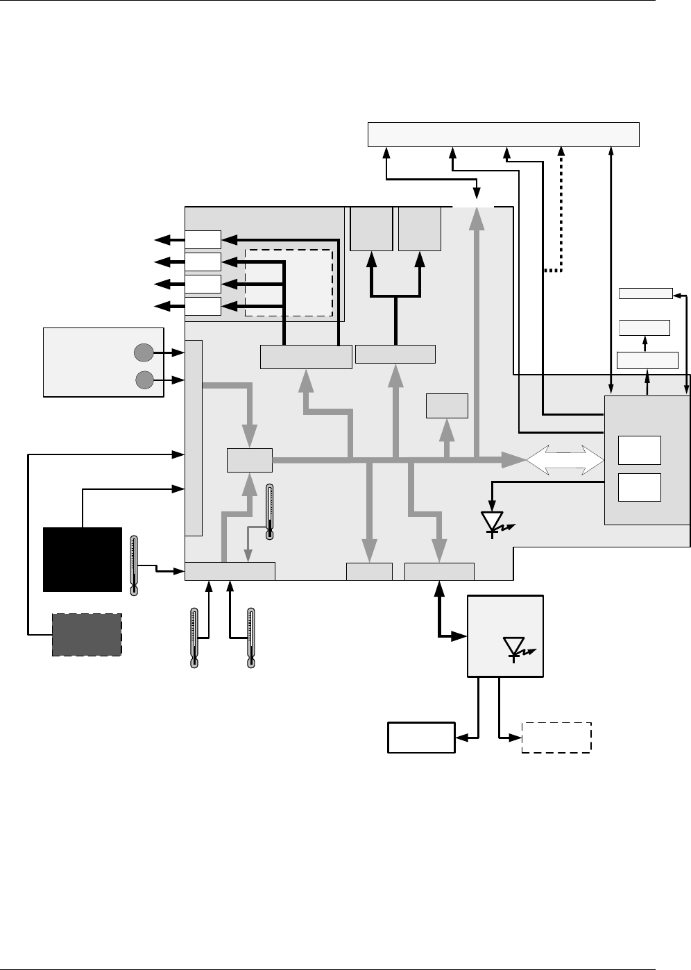
Finally, the CPU issues commands via a series of relays and switches (also over
the I
2
C bus) located on a separate printed circuit assembly to control the function
of key electromechanical devices such as heaters..
Flow/Pressure Sensor PCA
Optional CO
2
Sensor Heater
Analog Outputs
Aout 1
Aout 4
Analog Outputs
(D/A)
External Digital I/O
Power Up
Circuit
P
C
1
0
4
B
u
s
PC 104
CPU Card
Disk on
Module
Flash
Chip
Aout 3
Aout 2
TEST CHANNEL OUTPUT
Status
Outputs
1 - 8
Control
Outputs
1 – 6
Optional
Current
Loop
Outputs
CPU
Status
LED
I
2
C Bus
O
2
Cell
Heater
Thermistor Interface
Box
Temperature
Sample Flow
Sensor
A/D
Converter
RELAY PCA
I
2
C
Status
LED
O
2
Range 2
O
2
Range 1
MOTHERBOARD
Sample Pressure
Sensor
Sensor Inputs
CO
2
(optional)
O
2
Sensor
Optional CO
2
Sensor
Internal
Digital I/O
O
2
Concentration
O
2
Sensor
Temperature
CO
2
Sensor
Temperature
(Optionl)
BOX
Temperature
COM2
Female
RS232
Male
Ethernet
USB COM
port
ANALOG
IN
(
I
2
C Bus
)
COM1 (RS-232 only)
COM2 (RS-232 or RS-485)
or USB
Touchscreen
Dis
p
la
y
LVDS
transmitter
board
USB
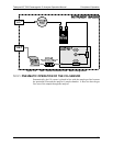
Figure 12-7: T802 Electronic Block Diagram
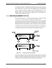
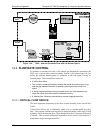
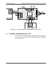
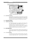
12.5.2. ELECTRONIC OPERATION OF THE CO
2
SENSOR
The CO
2
PCA is powered by 12 VDC from the analyzer via the relay card, which
outputs a 0-5 VDC analog signal to the analyzer’s CPU via the motherboard that
corresponds to the concentration of CO
2
measured by the probe.
07275B DCN6418