


Principles of Operation Teledyne API T802 Paramagnetic O
2
Analyzer Operation Manual
222
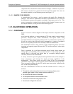
12.2.1. OPERATION WITHIN THE T802 ANALYZER
Operationally, the CO
2
sensor option is transparently integrated into the core
analyzer operation. All functions can be viewed or accessed through the front
panel, just like the functions for O
2
.
The CO2 concentration is displayed in the upper right-hand corner, alternating
with O2 concentration.
Test functions for CO2 slope and offset are viewable from the front panel along
with the analyzer’s other test functions.
CO2 sensor calibration is performed via the front panel CAL function and is
performed in a nearly identical manner as the standard O2 calibration. See
Section 9.5 for more details.
Stability of the CO2 sen
sor can be viewed via the front panel (see Section
9.5.3).
The CO
2
concentration range is 0-20%. See Section 9.5.1 for information on
calibrating the CO
2
.
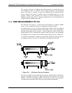
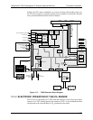
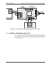
12.3. PNEUMATIC OPERATION
CAUTION
GENERAL SAFETY HAZARD
IT IS IMPORTANT THAT THE SAMPLE AIRFLOW SYSTEM IS BOTH LEAK-TIGHT AND NOT
PRESSURIZED OVER AMBIENT PRESSURE.
Regular leak checks should be performed on the analyzer as described in the maintenance
schedule, 10.1.
Procedures for correctly performing leak checks can be found in Section 10.3.3
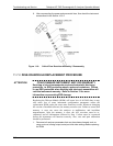
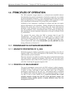
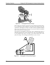
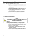
In pneumatic operation an internal pump evacuates the sample chamber creating a
small vacuum that draws sample gas into the analyzer. Normally the analyzer is
operated with its inlet near ambient pressure either because the sample is directly
drawn at the inlet or a small vent is installed at the inlet. There are several
advantages to this “pull through” configuration.
First the pumping process heats and compresses the sample air complicating
the measurement process. Both heat and pressure affect the accuracy of
paramagnetic O
2
measurements.
Additionally, certain physical parts of the pump itself are made of materials that
might chemically react with the sample gas.
07275B DCN6418